Milking apparatus and method

a technology of apparatus and milking machine, which is applied in the direction of milking devices, dairy products, catheters, etc., can solve the problems of inability to achieve milking, inability to effectively milk teats, and inability to effectively control the pressure (forces), so as to facilitate the use of the support structure, improve the control of pressure, and improve the effect of membrane tuning

Active Publication Date: 2011-08-23
MILKRITE INTERPULS LTD
View PDF29 Cites 8 Cited by
  • Summary
  • Abstract
  • Description
  • Claims
  • Application Information

AI Technical Summary

Benefits of technology

[0012]The support structure is not a fixed part of the outer body, so in other words may be a discrete component of the apparatus and adapted to be removable from the outer body. By providing such a separate support structure onto which the membranes may be mounted e.g. before they are inserted into the outer body, it is possible to design a support structure that is easy to manipulate and which allows the membranes to be placed under transverse tension more easily than is the case for the apparatus of the prior art. Note, however, that the present invention does not exclude the possibility that the support structure is positioned within the outer body before the membranes are mounted thereon.
[0013]Furthermore, the use of a support structure allows the milking apparatus to be assembled using a standard outer body component, which does not need to be adapted to hold the membranes of the liner under transverse tension.
[0040]Accordingly, the present invention provides a support structure which holds the membranes of the liner under transverse tension. As will be understood from the discussion above, it may be preferable that the support structure has a first tensioning element having two spaced-apart attachment points and a second tensioning element having two spaced apart attachment point. The first membrane may be attached or attachable to the first tensioning element of the support structure at the two spaced apart attachment points so that the first membrane is under tension in a direction transverse to the first direction. Similarly, the second membrane may be attached to the second tensioning element of the support structure at the two spaced-apart attachment points so that the second membrane is under tension in a direction transverse to the first direction when there is the same pressure across the membranes. This tensioning effect may be achieved by making the relaxed distance between attachment points on, for example, the first tensioning element of the support structure greater than the relaxed length of the first membrane which is to span these points and similarly for the second membrane and corresponding tensioning element. The attachment points of the support structure are spaced radially inward from the outer body.
[0043]The section between the two attachment points on each tensioning element may be either straight or curved, or have a peak. When curved or peaked elements are used, attachment of the membranes becomes easier, since the elements are capable of being flexed more easily than straight elements in order to bring the distance between the attachment points closer to the relaxed length of the membrane. Furthermore, using curved or peaked tensioning elements, particularly peaked elements, it is easier to tension the membranes at the low transverse stress levels preferred for milking, since the elements will tend to bend to relieve some of the tension in the membrane.
[0048]The resilient membranes may be put under axial tension (i.e. tension in the first direction), as well as transverse tension, in order to tune the membranes more effectively to the shape of the teat. In this case, it may be useful for the level of axial tension to be adjustable. Such tuning allows improved control over the pressures (forces) exerted on the teat and therefore may be used to ensure effective milking action, while optimizing teat health.
[0052]Normally, the space between the membranes will be subject to suction, in a way similar to the interior of known liners, while the region between the outside of the membranes and the interior of the body into which the membranes are received is periodically brought to atmospheric pressure in order for the liner to close around the teat, thus providing temporary relief from the suction forces and reducing teat congestion. However, it is possible instead to provide a periodic overpressure to the region between the membranes and the outer body, since it is believed that such a positive pressure is of beneficial effect, as it matches the internal pressure of the teat more closely. Furthermore, it is possible to use only over pressure without suction being applied to the interior of the liner.

Problems solved by technology

This partial vacuum draws milk from the teat, but also causes congestion of the teat tissues, arising from the accumulation of blood and other fluids.
One problem associated with the liner arrangement in the conventional apparatus described above is that, when the region between the body and the liner is brought to atmospheric pressure, the liner closes in tightly around the teat end, so that the end of the teat often experiences excessive local pressure.
Thus, the efficiency of the milking process is impaired by the need to avoid excessive force being applied to the teat end, so as to maintain teat health.
However, since these attachment points are only accessible from the interior of the body housing the liner, the process of affixing the membranes to the outer body, so that they are under transverse tension, is awkward and time-consuming.
Furthermore, the outer body often includes external attachments which make it difficult to manipulate.
Another problem is that the attachment of the liner membranes directly to the outer body requires the outer body, which is in general a standard component, to be specially adapted to hold the membranes.

Method used


Image

  • Milking apparatus and method
  • Milking apparatus and method
  • Milking apparatus and method

Examples


Embodiment Construction

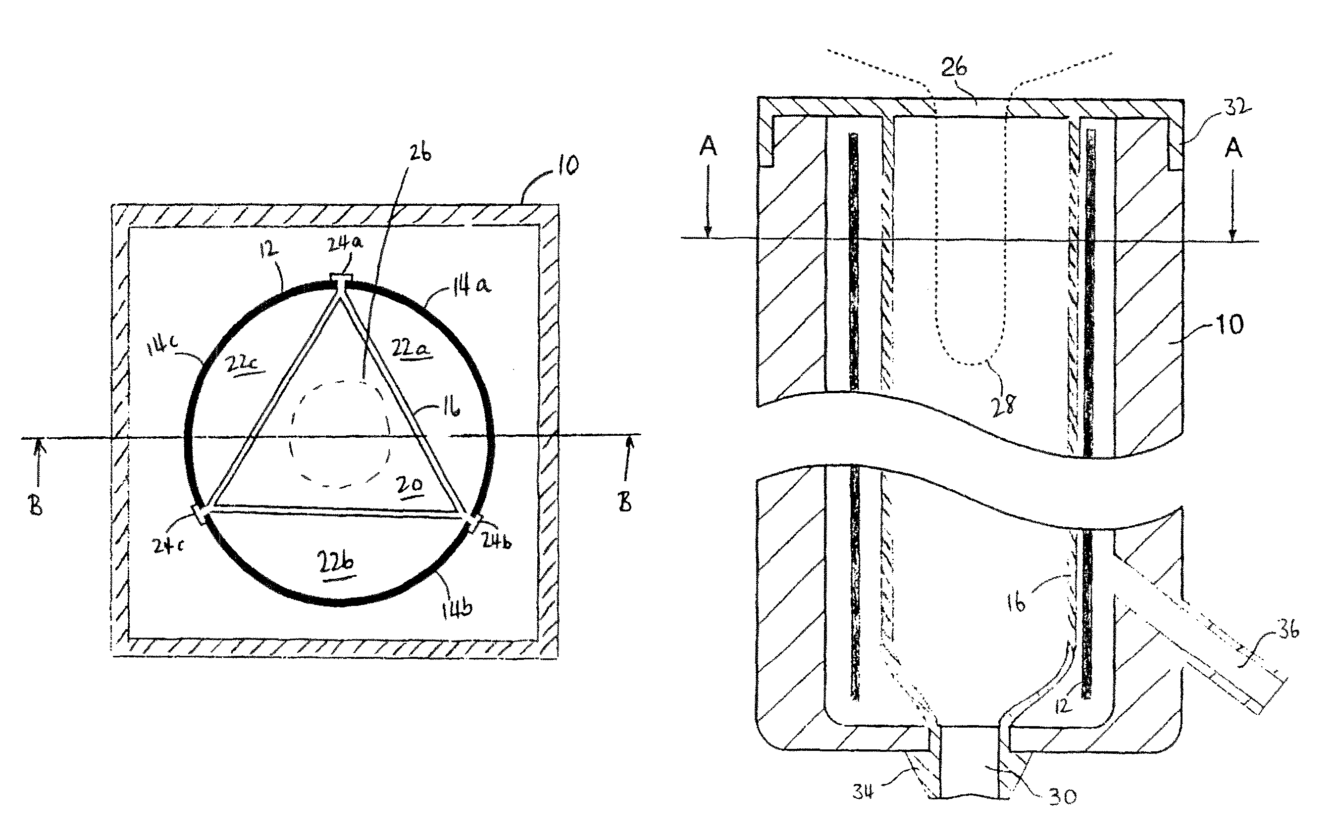
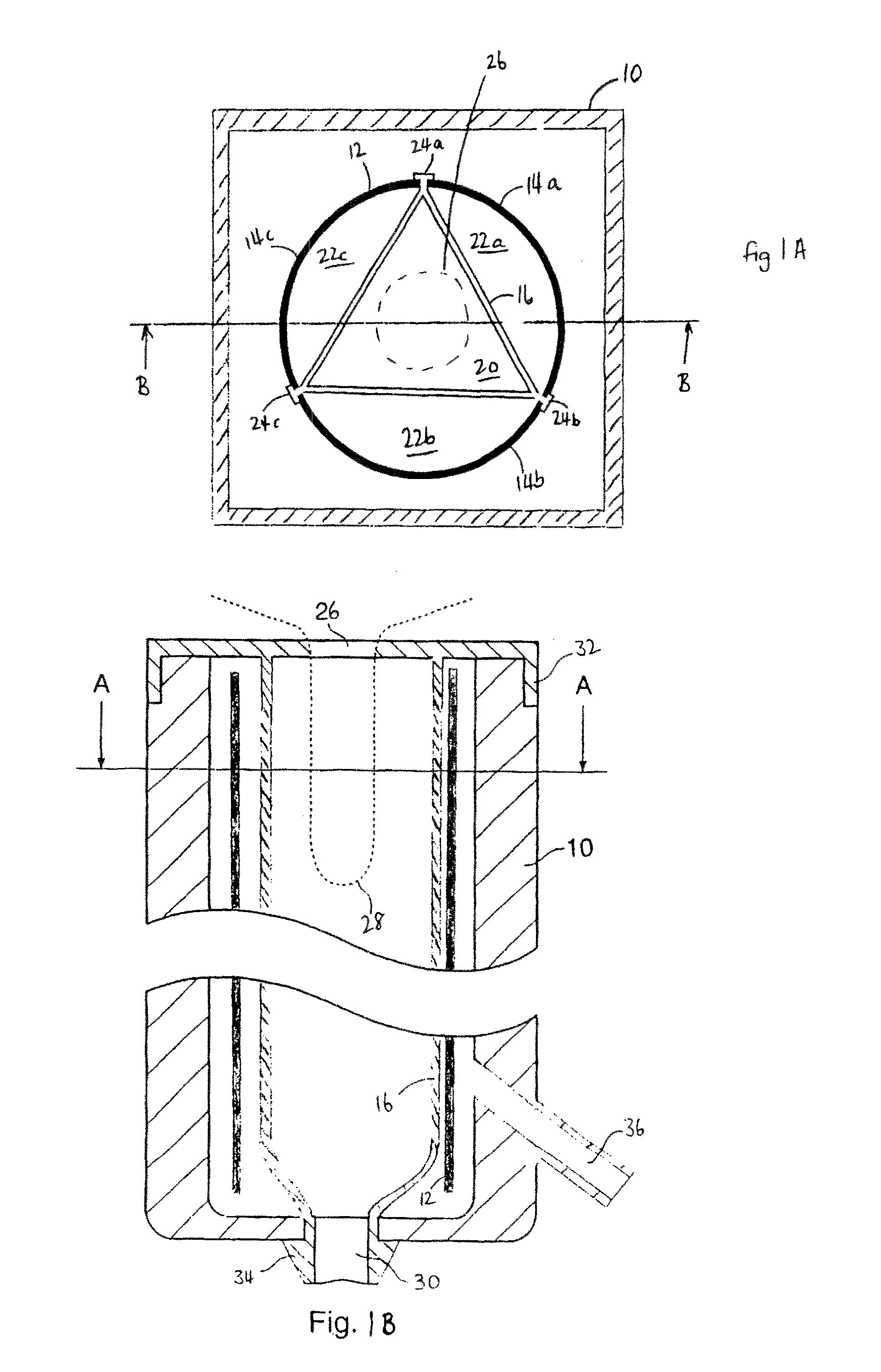
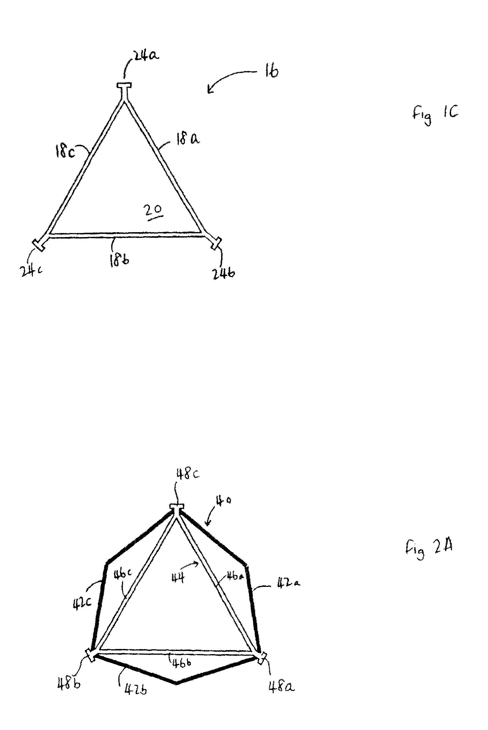
[0060]Referring first to FIGS. 1A, 1B, and 1C, a milking apparatus comprises an outer body 10, the interior of which is hollow and which contains a support structure 12, into which is mounted a liner 16. The support structure has three tensioning elements 14a, 14b, 14c corresponding to the three resilient membranes 18a, 18b, 18c of the liner 16. The three membranes 18a, 18b, 18c of the liner 16 are joined at their longitudinal edges to define a space 20 therebetween which is triangular in transverse section and further spaces 22a, 22b, 22c, which are each bounded by one of the membranes 18a, 18b, 18c and the corresponding tensioning element 14a, 14b, 14c of the support structure 12. Locks 24a, 24b, 24c at the longitudinal joins of the membranes 18a, 18b, 18c allow each membrane to be clipped at its edges to tensioning elements 14a, 14b, 14c of the support structure.

[0061]In this embodiment, each lock 24a, 24b, 24c is clipped to two tensioning elements 14a, 14b, 14c of the support st...


PUM


Abstract

The invention relates to apparatus for milking animals such as cows, components of the apparatus and methods of milking animals employing the apparatus. The apparatus comprises at least two resilient membranes having a space therebetween into which the teat of the animal may be inserted. The membranes are held by a support structure under tension in a direction transverse to the direction of insertion of the teat, to protect the teat from excessive force when the membranes fall onto the teat.

Description

CROSS-REFERENCE TO RELATED APPLICATION[0001]This application claims the benefit of GB0716800.8, filed Aug. 29, 2007, which is incorporated herein by reference in its entirety. This application is also related to U.S. patent application Ser. No. 11 / 252,268, filed Oct. 17, 2005.BACKGROUND OF THE INVENTION[0002]1. Field of the Invention[0003]The present invention relates to a milking apparatus, i.e. an apparatus for removing milk from a teat of an animal, such as a cow, sheep, goat, horse, buffalo, or camel. It also relates to a method of use of such an apparatus.[0004]2. Summary of the Prior Art[0005]In a conventional milking apparatus, a cylindrical liner of resilient material is housed within an outer body, and the liner is tensioned along the axis of the cylinder. The teat of the animal is then inserted through an opening in the body into the cylindrical liner, and then suction is applied to another opening in the body, at the other end of the cylindrical liner to that in which the...

Claims


Application Information

Patent Timeline
Patent Type & Authority Patents(United States)
IPC IPC(8): A01J3/00A01J5/04
CPCA01J5/08A01J5/04
Inventor BOAST, DAVID
Owner MILKRITE INTERPULS LTD
Why Eureka
Try Eureka