
Multi-wavelength signal generation device and multi-wavelength light generation method

a signal generation device and multi-wavelength technology, applied in the direction of light demodulation, instruments, electrical equipment, etc., can solve the problems of inability to determine whether the test is performed appropriately, the apparatus becomes complicated, and the test cannot be deemed appropriately

Active Publication Date: 2011-08-23
NAT INST OF INFORMATION & COMM TECH
View PDF9 Cites 1 Cited by
  • Summary
  • Abstract
  • Description
  • Claims
  • Application Information

AI Technical Summary

Benefits of technology

[0009]It is an object of the present invention to provide a multiple wavelength signal generation device capable of generating lights having more information by using the above-mentioned conventional optical comb generator, and a generation method for multiple wavelength light using such a light source.
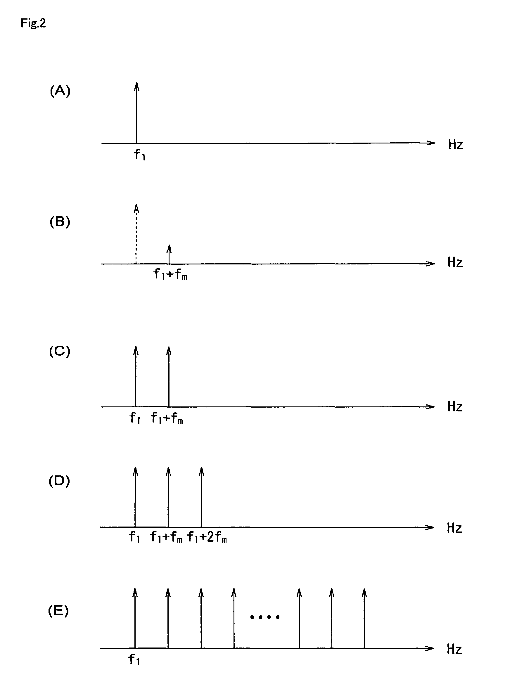
[0013]Only an unmodulated single light has been inputted to the conventional optical comb generator. However, it is found that when a light whose phase, intensity, and frequency are modulated is inputted as in the present invention, more information can be transmitted, an in addition, the lights do no interfere with one another. Namely, according to the present invention, a lot of lights with more information and having different optical frequencies can be obtained compared to a multiple wavelength signal generation device using the conventional optical comb generator.
[0015]According to the present invention, it is made possible to provide a multiple wavelength signal generation device capable of obtaining multiple wavelength lights that can be utilized for a wavelength multiplexed optical communication system and the like.

Problems solved by technology

However, a multiple wavelength signal generation device using them is required to stabilize an optical path, so that the apparatus becomes complicated.
Also, since the super continuum light source uses the mode-locked laser, there is a similar problem as that of the mode-locked laser.
When the device for the wavelength multiplexed optical transmission system is tested by using such multiple wavelength lights, since the test has been performed by using the lights having the same optical phase or the like, it cannot be deemed that the test is performed appropriately.
Therefore, as in the above example, it cannot be deemed that a test is performed appropriately.

Method used


Image

  • Multi-wavelength signal generation device and multi-wavelength light generation method
  • Multi-wavelength signal generation device and multi-wavelength light generation method
  • Multi-wavelength signal generation device and multi-wavelength light generation method

Examples


embodiment 1

[0032]Hereinafter, the present invention will be specifically described using embodiments. FIG. 3 is a schematic diagram of a multiple wavelength signal generation device used in an embodiment 1. The input lights are lights whose wavelengths are 1550 nm and their respective intensities are 1 mW. Also, the frequency of the electric signal provided to the optical SSB modulator is 10 GHz. An optical amplifier using a fluoride EDF is provided within the loop to compensate a loss of light associated with the wavelength conversion at the optical SSB modulator. The wavelength interval is 0.08 nm for 10 GHz. The multiple wavelength signal generation device shown in FIG. 3 is used to perform more than 120 circles, whereby an optical comb covering a range of approximately 10 nm for the respective input lights. It is to be noted in FIG. 3 that TLS denotes a light source that can be modulated (Tunable Laser Source). PC denotes a Polarization Controller. Circ denotes a Circulator. T-FBG denotes ...


PUM

PropertyMeasurementUnit
frequenciesaaaaaaaaaa

Abstract

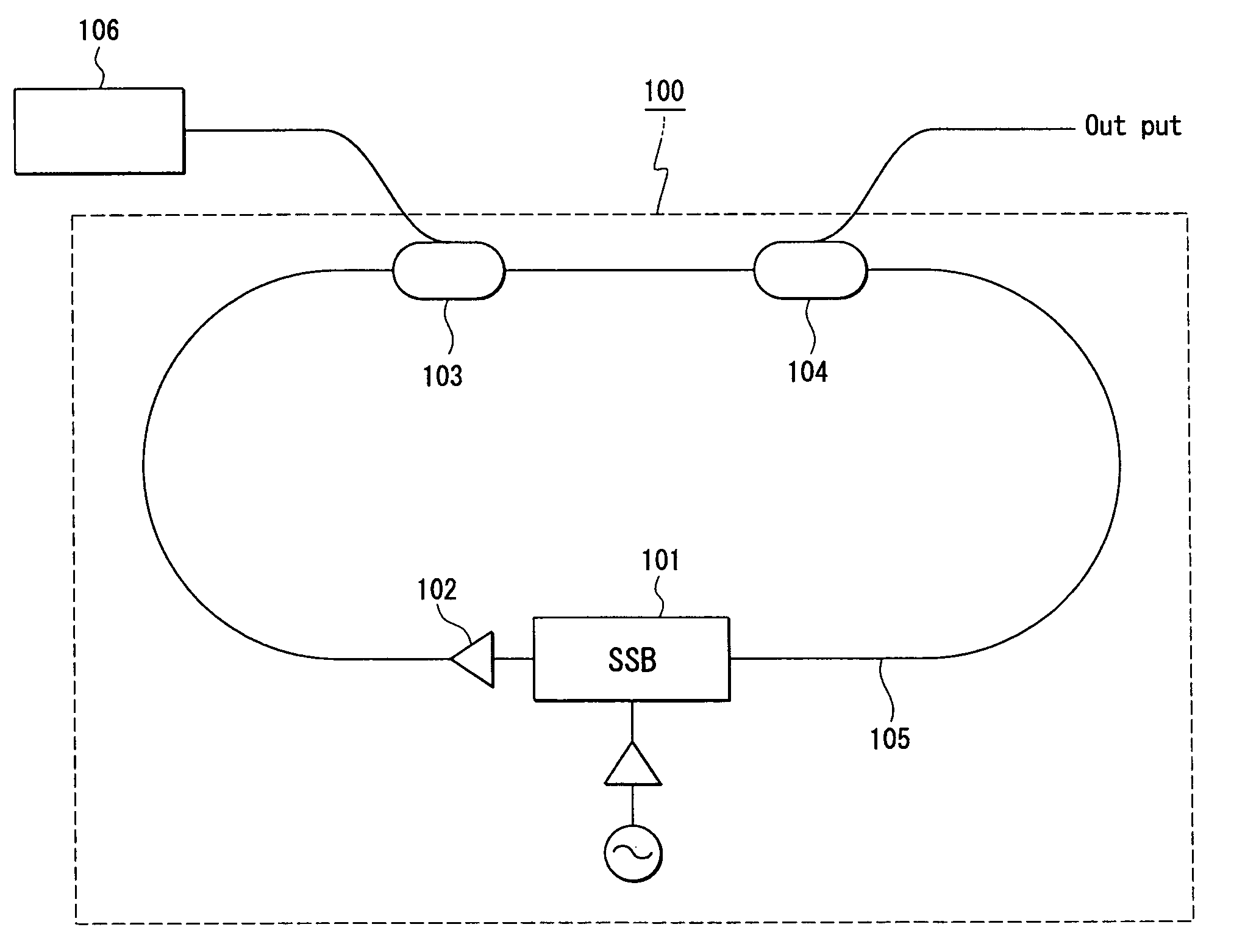
A multiple wavelength signal generation device of the present invention is a multiple wavelength signal generation device having an optical comb generator for obtaining an input light and a group of lights shifted from the input light by predetermined frequencies; and an optical adjusting portion adjusting lights to be inputted to the optical comb generator; wherein the optical comb generator is composed of an optical fiber loop (105) which is provided with an optical SSB modulator (101), an optical amplifier (102) for compensating a conversion loss at the optical SSB modulator, an optical input port (103) for inputting lights from the light source, and an optical output port (104) for outputting lights, and the optical adjusting portion is composed of a phase modulator, an intensity modulator, or a frequency modulator.

Description

TECHNICAL FIELD[0001]The present invention relates to a multiple wavelength signal generation device and a generation method for multiple wavelength light.BACKGROUND ART[0002]A multiple wavelength signal generation device can be used as a light source for a wavelength multiplexed transmission system, a reference light source for measurement, and the like. Therefore, various types of multiple wavelength signal generation devices have been proposed. As specific multiple wavelength signal generation devices, one having integrated numerous semiconductor lasers (LD), a super continuum light source utilizing non-linearity of a fiber, a mode-locked laser using a fiber ring, and an optical comb generator using a Fabry-Perot optical modulator are known.[0003]For the mode-locked laser and the Fabry-Perot optical modulator, phase relationships between wavelength contents are determined, and wavelength intervals are accurately constant. However, a multiple wavelength signal generation device us...

Claims


Application Information

Patent Timeline
Patent Type & Authority Patents(United States)
IPC IPC(8): H04B10/00G02F1/03G02F1/37G02F2/02
CPCG02F2/02H04B10/506G02F2203/56
Inventor KAWANISHI, TETSUYAIZUTSU, MASAYUKI
Owner NAT INST OF INFORMATION & COMM TECH
Learn More