Treatment device with guidable needle

a treatment device and needle technology, applied in the direction of catheters, surgical forceps, therapy, etc., can solve the problems of frequent urination, difficult precise placement of treatment probes, obstruction of urinary tract, etc., and achieve the effect of minimizing trauma and greater medical benefi

Inactive Publication Date: 2007-04-10
LUNDQUIST INGEMAR H +1
View PDF77 Cites 91 Cited by
  • Summary
  • Abstract
  • Description
  • Claims
  • Application Information

AI Technical Summary

Benefits of technology

[0011]It is an object of this invention to provide a device and method for penetrating tissue, through intervening tissues to the precise target tissue selected for a medical action

Problems solved by technology

Often, precise placement of a treatment probe is difficult because of the location of targeted tissues in the body or the proximity of the target tissue to easily damaged, critical body organs, nerves, or other components.
Hyperplastic enlargement of the prostate gland often leads to compression of the urethra, resulting in obstruction of the urinary tract and the subsequent development of symptoms including frequent urination, decrease in urinary flow, nocturia, pain, discomfort, and dribbling.
Currently there is no proven effective nonsurgical method of treatment of BPH.
In addition, the surgical procedures available are not totally satisfactory.
Those suffering from BPH are often elderly men, many with additional health problems which increase the risk of surgical procedures.
Surgical procedures for the removal of prostatic tissue are associated with a number of hazards including anesthesia related morbidity, hemorrhage, coagulopathies, pulmonary emboli and electrolyte imbalances.
These procedures performed currently can also lead to cardiac complications, bladder perforation, incontinence, infection, urethral or bladder neck stricture, retention of prostatic chips, retrograde ejaculation, and infertility.
Due to the extensive invasive nature of the current treatment options for obstructive uropathy, the majority of patients delay de

Method used


Image

  • Treatment device with guidable needle
  • Treatment device with guidable needle
  • Treatment device with guidable needle

Examples


Embodiment Construction

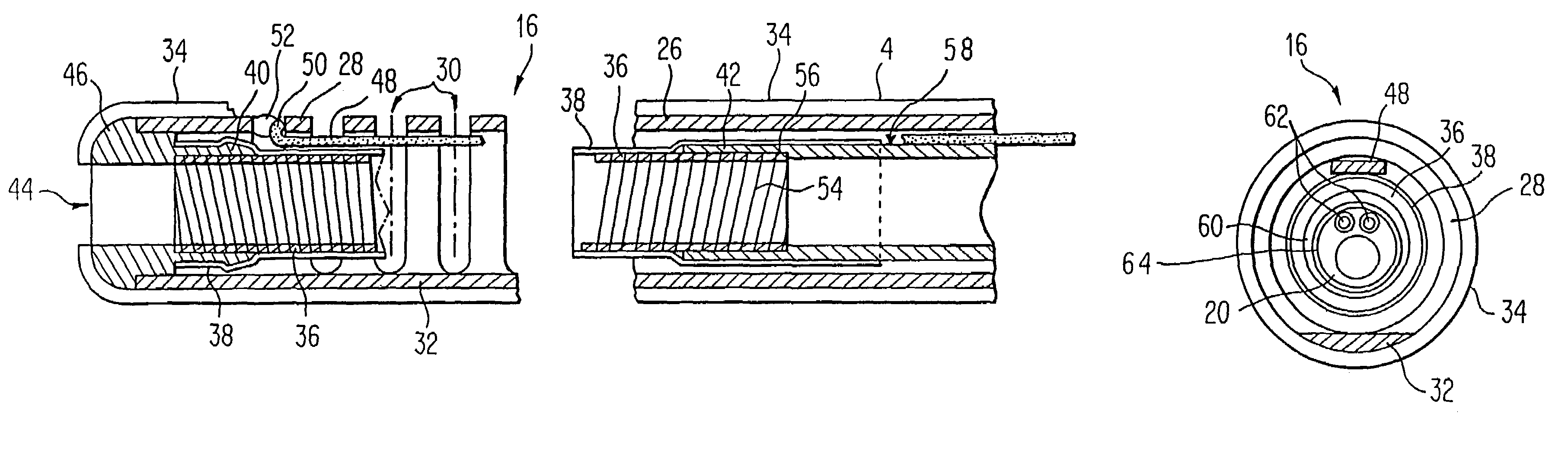
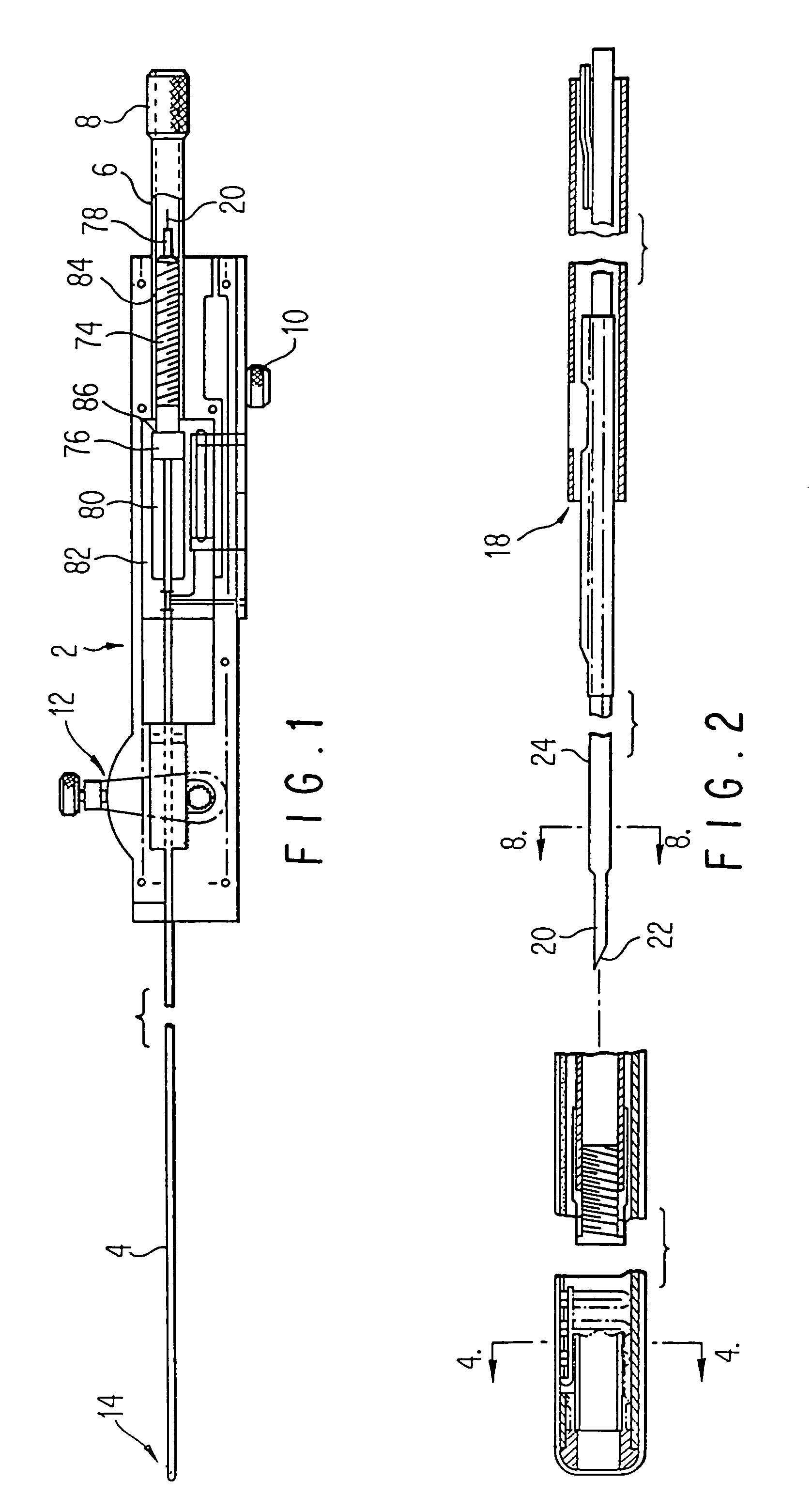
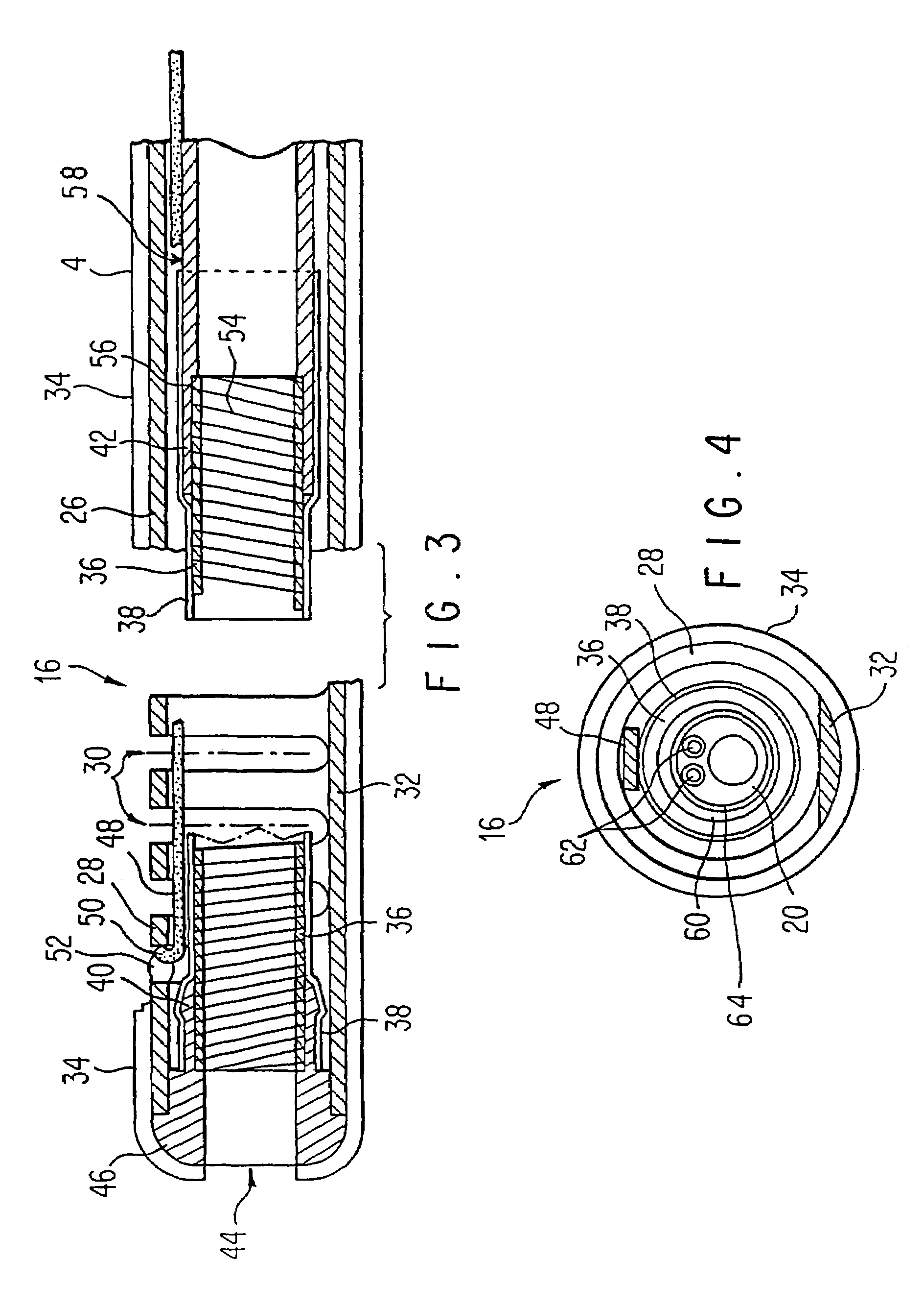
[0050]The device of this invention provides a precise controlled positioning of a treatment stylet in a tissue targeted for treatment, destruction or sampling from a cannula positioned in the vicinity of the target tissue.

[0051]The term “stylet” as used hereinafter is defined to include both solid and hollow probes which are adapted to be passed from a cannula port through normal tissue to targeted tissues. The stylet is shaped to facilitate easy passage through tissue. It can be a solid wire, thin rod, or other solid shape or it can be a thin hollow tube or other shape having a longitudinal lumen for introducing fluids to or removing materials from a site. The stylet can also be a thin hollow tube or other hollow shape, the hollow lumen thereof containing a reinforcing or functional rod or tube such as a laser fiber optic. The stylet preferably has a sharpened end to reduce resistance and trauma when it is pushed through tissue to a target site.

[0052]The stylet can be designed to p...


PUM


Abstract

A medical treatment device comprising an elongate probe member having proximal and distal extremities. The elongate probe member has a longitudinal axis and at least one passageway extending from the proximal extremity to the distal extremity. A guide is mounted in the at least one passage of the elongate probe member and has proximal and distal extremities with the distal extremity of the guide being in the vicinity of the distal extremity of the elongate probe member. The guide has an opening in the distal extremity and a lumen extending from the proximal extremity to the opening in the distal extremity. A needle is slidably disposed in the lumen of the guide. The needle is in the form of a tube having an axial lumen extending therethrough. A control mechanism is coupled to the proximal extremity of the elongate probe member and is secured to the needle for advancing and retracting the needle relative to the guide.

Description

RELATIONSHIP TO COPENDING APPLICATION[0001]This is a continuation of application Ser. No. 09 / 085,313 filed May 27, 1998, now U.S. Pat. No. 6,102,886 which is a continuation of application Ser. No. 08 / 667,452 filed Jun. 21, 1996; now U.S. Pat. No. 5,848,986, which is a continuation of application Ser. No. 08 / 420,304 filed Apr. 11, 1995, now U.S. Pat. No. 5,531,667; which is a continuation of application Ser. No. 08 / 109,190 filed Aug. 19, 1993, now U.S. Pat. No. 5,409,453; which is a continuation-in-part of Ser. No. 07 / 929,638 filed Aug. 12, 1992, abandoned, and a continuation-in-part of Ser. No. 08 / 012,370 filed Feb. 2, 1993, now U.S. Pat. No. 5,370,675, and a continuation-in-part of Ser. No. 08 / 062,364 filed May 13, 1993, now U.S. Pat. No. 5,435,805, and a continuation-in-part of Ser. No. 08 / 061,647 filed May 13, 1993, now U.S. Pat. No. 5,421,819, and a continuation-in-part of Ser. No. 08 / 061,072 filed May 14, 1993, now U.S. Pat. No. 5,385,544, and a continuation-in-part of Ser. No....

Claims


Application Information

Patent Timeline
IPC IPC(8): A61B17/20A61B10/00A61B10/02A61B10/06A61B17/00A61B17/22A61B17/24A61B17/28A61B17/34A61B18/00A61B18/08A61B18/14A61B18/18A61B18/22A61B18/24A61B19/00A61F7/00A61M1/00A61M3/02A61M25/00A61M25/01A61M25/092A61N1/06A61N1/40A61N5/04
CPCA61B10/0233A61B10/0275A61B10/06A61B17/3403A61B17/3417A61B17/3478A61B18/00A61B18/1477A61B18/1485A61B18/18A61B18/1815A61M25/0136A61M25/0138A61M25/0147A61N1/06A61N1/40A61N1/403A61N5/045A61B10/02A61B10/0241A61B18/14A61B18/1442A61B18/148A61B18/1492A61B18/24A61B2017/00084A61B2017/00092A61B2017/00101A61B2017/00106A61B2017/00123A61B2017/00181A61B2017/00194A61B2017/00274A61B2017/00292A61B2017/003A61B2017/00469A61B2017/00867A61B2017/22072A61B2017/22077A61B2017/22082A61B2017/248A61B2017/2939A61B2017/3488A61B2018/00005A61B2018/00011A61B2018/00083A61B2018/00095A61B2018/00101A61B2018/00196A61B2018/0022A61B2018/00547A61B2018/00577A61B2018/00678A61B2018/00702A61B2018/00726A61B2018/00744A61B2018/00761A61B2018/00791A61B2018/00797A61B2018/00821A61B2018/00886A61B2018/0091A61B2018/00916A61B2018/00946A61B2018/00982A61B2018/1253A61B2018/126A61B2018/1273A61B2018/128A61B2018/1425A61B2018/2238A61B2019/4873A61B2019/5217A61B2019/5276A61B2019/5278A61B2019/5282A61B2019/5425A61B2217/005A61M3/0279A61M25/0068A61M25/008A61M25/0082A61M2025/0086A61M2025/0087A61M2025/0089A61M2025/0096A61M2025/018A61N5/04A61B2090/3782A61B2090/3786A61B2090/3614A61B2090/0814A61B2090/378A61B2090/3925
Inventor LUNDQUIST, INGEMAR H.EDWARDS, STUART D.
Owner LUNDQUIST INGEMAR H
Why Eureka
Try Eureka