Faucet control system and method

a control system and faucet technology, applied in the field of faucets, can solve the problems of increasing energy costs, increasing energy costs, and expensive retrofitting of existing washrooms, and achieve the effects of facilitating a wider range of temperatures, preventing energy wastage, and hot water flow

Active Publication Date: 2011-08-30
BOEY KUM F
View PDF43 Cites 33 Cited by
  • Summary
  • Abstract
  • Description
  • Claims
  • Application Information

AI Technical Summary

Benefits of technology

[0007]In one embodiment, a first sensor is placed anywhere above the sink, such as on the right side of the spout of the sink. An electronic eye may be directed near or below the tip of the faucet spout. When a user approaches the sink to wash hands, water flow is immediately activated. Optionally, the initial water flow may be cold water, to prevent energy wastage. A second sensor may be placed elsewhere on the sink, such as on the left hand side of the faucet spout. Consequently, while the right hand, for example, is still below the faucet spout, the water flow is activated with the first sensor. The temperature of the water may be changed by, for example, waiving the left hand above the second sensor. The hot valve and cold valve, for example, may then open to allow hot and cold water to mix to create a warm temperature flow. If the user wishes hot water, the user will then waive his or her hands over the second sensor again, which will close the cold valve and open only the hot valve, thus allowing only hot water to flow from the spout.

Problems solved by technology

Many touchless control systems, however, lack a means for convenient adjustment of water temperature.
Touchless control systems that have no temperature control can be installed to dispense only warm water, for example, but this increases energy costs when warm water is not needed.
Or the system can be set to dispense only cold water, but this can be quite unpleasant during winter months.
Another drawback of existing faucet control systems is that installation often requires replacement of the faucet spout, which makes retrofitting of existing washrooms expensive.
Retrofitting is further complicated when removal of conventional hot and water control knobs on either side of the faucet spout exposes unsightly holes on a countertop.
Installing caps with no other purpose than to cover the holes is often undesirable, such as in luxury hotels and other locations where a finished appearance is important, because such caps draw attention to the fact that a retrofit was performed.

Method used


Image

  • Faucet control system and method
  • Faucet control system and method
  • Faucet control system and method

Examples


Embodiment Construction

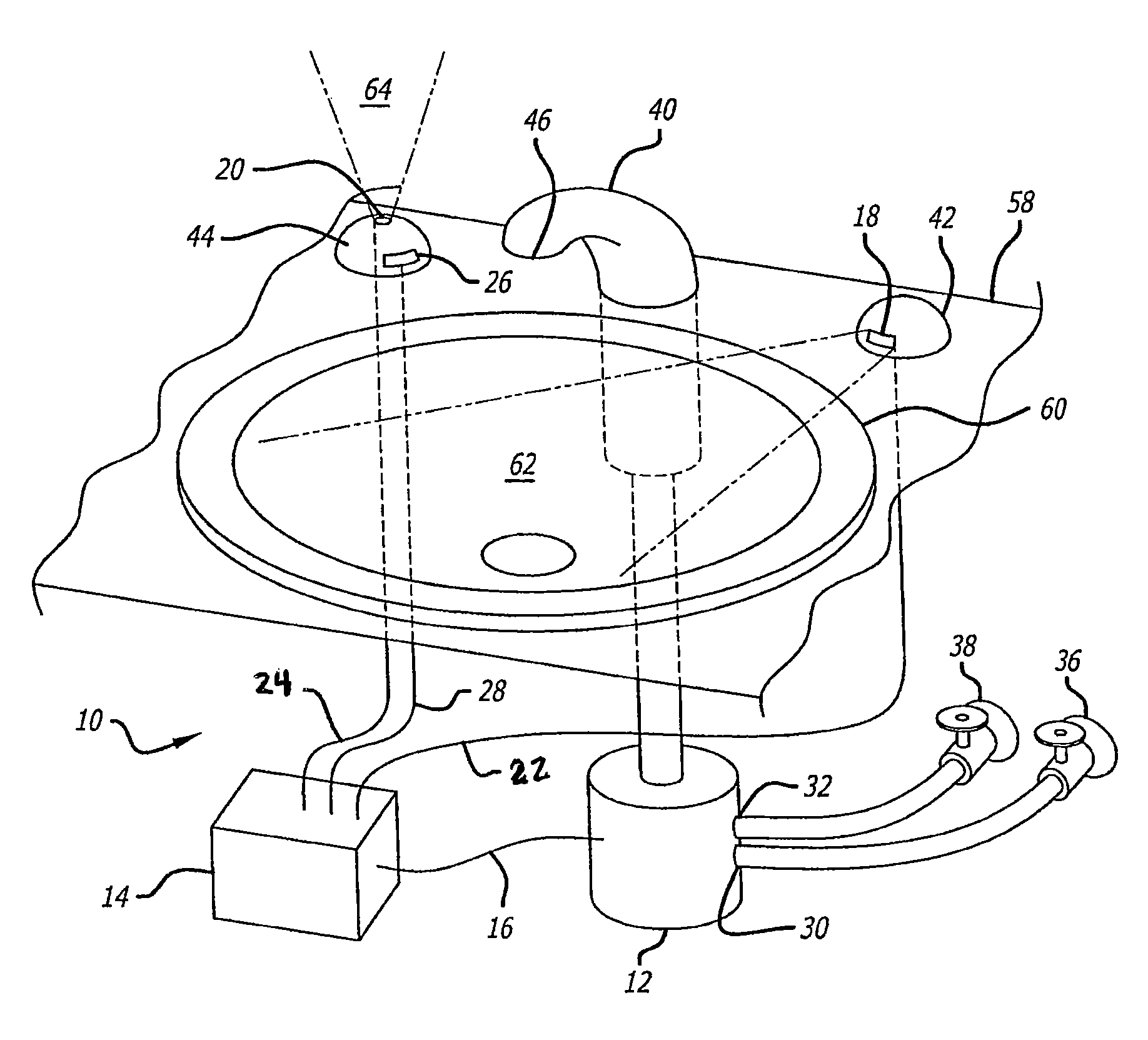
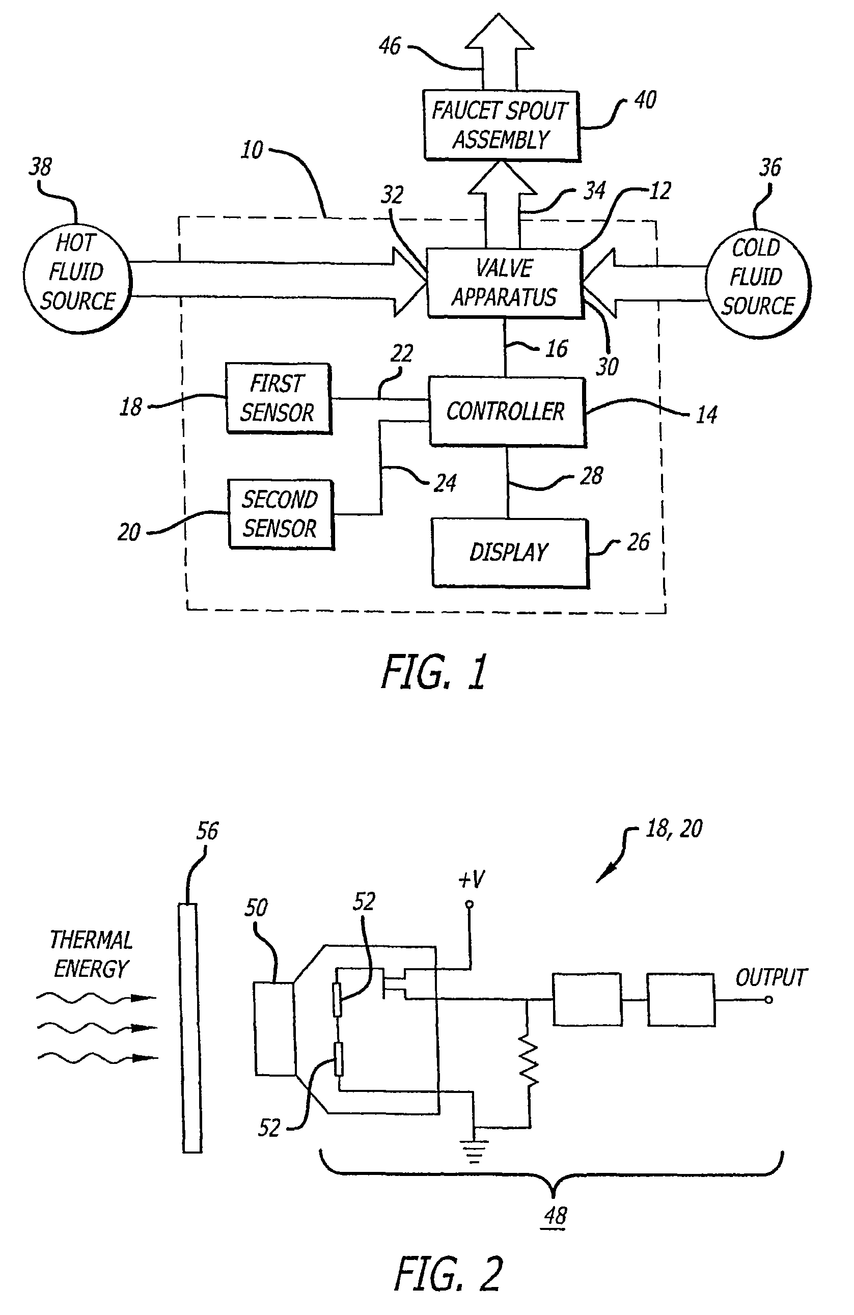
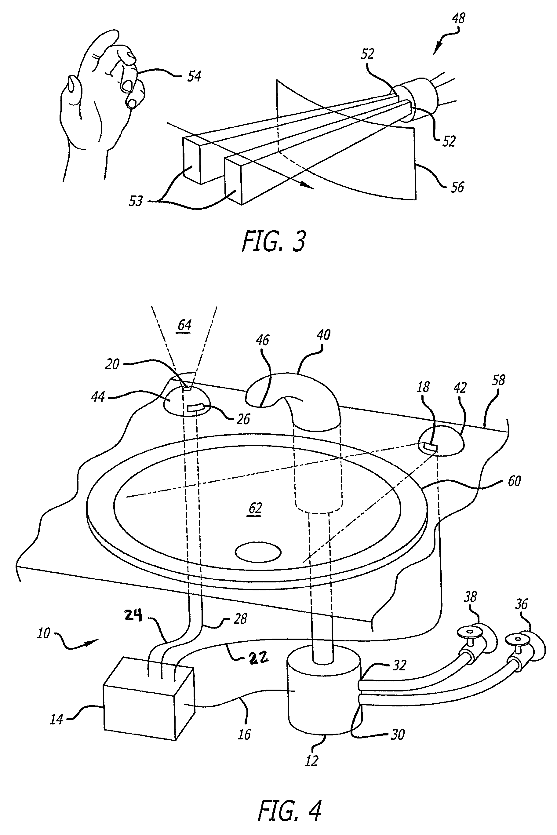
[0030]Referring now in more detail to the exemplary drawings for purposes of illustrating embodiments of the invention, wherein like reference numerals designate corresponding or like elements among the several views, there is shown in FIG. 1 a block diagram of a faucet control system 10 having a valve apparatus 12 controlled by a controller 14 that provides a valve control signal 16 to the valve apparatus. The faucet control system also has a first sensor 18 and a second sensor 20 that provide a first sensor signal 22 and a second sensor signal 24, respectively, to the controller. The faucet control system further has a visual display 26 for indicating temperature information in response to a display signal 28 from the controller.

[0031]The valve apparatus 12 has a cold fluid inlet 30, a hot fluid inlet 32, and a fluid outlet 34. A cold fluid source 36 and a hot fluid source 38 are in fluid communication with the cold and hot fluid inlets, respectively. A faucet spout assembly 40 is...


PUM


Abstract

A faucet control system comprises a valve apparatus, sensors or a motion detector to be activated by a user, and a controller that controls the valve apparatus. A first sensor may start fluid flow and a second sensor may alter the proportion of fluids delivered from two fluid sources. The sensors may be activated without being touched and may include infrared and / or photodiode sensing elements. In a sink embodiment, when a user approaches the sink to wash hands, water flow is activated. Optionally, the initial water flow may be cold water, to prevent energy wastage. A second sensor may be placed elsewhere on the sink, such as on the left hand side of the faucet spout. Consequently, when the right hand, for example, is placed below the faucet spout, the water flow is activated with the first sensor. The left hand may be placed above a second sensor and, by waiving the left hand, the hand sensor will cause the hot valve to allow hot water to mix with cold water from the cold valve, should the user wish a warm temperature water flow. If the user wishes hot water, the user will then waive his or her hands over the second sensor, which will close the cold valve and open only the hot valve, thus allowing only hot water to flow from the spout.

Description

CROSS-REFERENCES TO RELATED APPLICATIONS[0001]This application claims the benefit of U.S. Provisional Application No. 60 / 855,002, filed Oct. 27, 2006, and U.S. Provisional Application No. 60 / 883,970, filed Jan. 8, 2007, both of which are incorporated by reference. This application is a continuation-in-part of International Application No. PCT / US2007 / 070939, filed Jun. 12, 2007 and which is incorporated by reference.FIELD OF THE INVENTION[0002]The invention relates generally to faucets, and, more particularly, to a control system and method for controlling fluid flow to faucets.BACKGROUND OF THE INVENTION[0003]In many settings it is desirable to have a control system that allows for convenient control of water faucets and other water delivery fixtures. Touchless control systems have been developed which allow water flow from a faucet when a person places his or her hand within range of an infrared sensor. Touchless control systems promote sanitary conditions because they eliminate th...

Claims


Application Information

Patent Timeline
Patent Type & Authority Patents(United States)
IPC IPC(8): E03C1/05G05D7/00
CPCE03C1/057Y10T137/0486Y10T137/86389
Inventor BOEY, KUM F
Owner BOEY KUM F
Why Eureka
Try Eureka