Device and method for treating organic waste gas through synergistic catalysis of plasma

A plasma and organic waste gas technology, applied in chemical instruments and methods, gas treatment, separation methods, etc., can solve problems such as changes in waste gas components, energy waste, and increased operating costs, so as to avoid energy waste and secondary pollution , the effect of shortening the contact time

Pending Publication Date: 2017-12-08
HUATIAN ENG & TECH CORP MCC +1
View PDF5 Cites 10 Cited by
  • Summary
  • Abstract
  • Description
  • Claims
  • Application Information

AI Technical Summary

Problems solved by technology

However, the hours of operation of all emission sources are not exactly the same, which causes the composition of the exhaust gas entering the treatment unit to change over time
The operating parameters of most existing plasma

Method used


Image

  • Device and method for treating organic waste gas through synergistic catalysis of plasma

Examples


Example Embodiment

[0037] Example 1

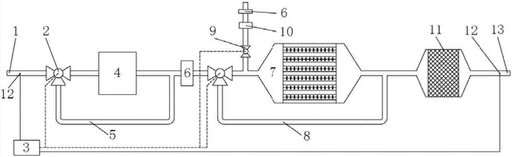
[0038] The exhaust gas enters the exhaust gas inlet 1, and is detected by the gas analyzer 3. The concentration of HCl in the exhaust gas is 100 ppm, and the concentration of TVOC is 500 ppm. The gas analyzer 3 sends a signal to control the electric valve 9 to close, and the opening direction of the electric three-way valve 3 is adjusted to a suitable position.

[0039] The exhaust gas enters the absorption tower 4 through the first electric three-way valve 2 . The absorption tower 4 is a spray absorption tower, and the absorption liquid is 2% NaHCO 3 solution. The exhaust gas is purified by the absorption tower 4 and then enters the filter device 6 to remove solid particles and liquid droplets, and at the same time, the gaseous water content in the exhaust gas decreases. After that, the exhaust gas enters the plasma reactor 7 through the second electric three-way valve 2 , is activated and partially oxidized, and then enters the catalytic reactor 11 , ...

Example Embodiment

[0040] Example 2

[0041] The exhaust gas enters the exhaust gas inlet 2, and is detected by the gas analyzer 3, and the exhaust gas does not contain acid waste gas such as HCl or NH 3Alkaline waste gas, TVOC concentration of 500ppm. The gas analyzer 3 sends a signal to control the electric valve 9 to close, and the opening direction of the electric three-way valve 3 is adjusted to a suitable position. The exhaust gas enters the parallel bypass 5 of the absorption tower through the first electric three-way valve 2, and then passes through the filter device 6 to remove the particulate matter, and then enters the plasma reactor 7 through the second electric three-way valve 2. After being activated and partially oxidized, the exhaust gas enters the catalytic reactor 11 and finally exits the device through the exhaust gas outlet 13 . As detected by the gas analyzer 3, the TVOC concentration at the exhaust gas outlet 13 was reduced to 45ppm.

Example Embodiment

[0042] Example 3

[0043] The exhaust gas enters the exhaust gas inlet 2, and is detected by the gas analyzer 3. The NH in the exhaust gas is detected by the gas analyzer 3. 3 The concentration is 80ppm and the TVOC concentration is 150ppm. The gas analyzer 3 sends a signal to control the opening of the electric valve 9, and the opening of the electric three-way valve 3 is adjusted to a suitable position. The exhaust gas enters the absorption tower 4 through the first electric three-way valve 2, and the absorption tower 4 is a spray absorption tower, and the absorption liquid used is 1% H 2 SO 4 solution. The exhaust gas is purified by the absorption tower 4 and then enters the filter device 6 to remove solid particles and liquid droplets, and the gaseous water content in the exhaust gas decreases. Then the exhaust gas enters the parallel bypass 8 of the plasma reactor through the second electric three-way valve 2 . At the same time, the outside air enters the plasma rea...


PUM


Abstract

The invention discloses a device and method for treating organic waste gas through synergistic catalysis of plasma. The device comprises an absorbing tower, a plasma reactor, a catalytic reactor and a gas analysis instrument, wherein the absorbing tower, a plasma reactor, a catalytic reactor are sequentially connected; a controlled three-way valve is arranged at a gas inlet of the absorbing tower and is used for respectively communicating a waste gas inlet with gas inlet of the absorbing tower or the waste gas inlet with a bypath of the absorbing tower; a controlled three-way valve is arranged at a gas inlet of the plasma reactor and is used for respectively communicating a gas outlet of the absorbing tower with a gas inlet of the plasma reactor or the gas outlet of the absorbing tower with a bypath of the plasma reactor; a detection point is arranged at a waste gas inlet, the gas analysis instrument is used for detecting waste gas in real time through the detection point, outputting control signals to the controlled three-way valves according to a detection result and controlling the switching of the controlled three-way valve. According to the device, the operation states of an airflow path and each processing unit are automatically controlled according to waste gas components, so that the unnecessary energy wasting is avoided.

Description

technical field [0001] The invention relates to the technical field of organic waste gas purification, in particular to a method and a device for plasma cooperative catalytic treatment of organic waste gas. Background technique [0002] Organic waste gas mostly comes from petrochemical, pharmaceutical, rubber, electronics, printing, spraying and other industries, and generally has the characteristics of complex components, flammable, explosive, toxic, and difficult to deal with. The treatment methods of organic waste gas include condensation method, absorption method, adsorption method, thermal incineration method, catalytic oxidation method, plasma method, biological method, etc. These methods have their own concentration ranges. Due to the complexity of the composition, organic waste gas is generally treated with the combination of the above methods. [0003] The plasma method has the advantages of high removal efficiency and convenient operation, but when treating some p...

Claims


Application Information

Patent Timeline
IPC IPC(8): B01D53/14B01D53/18B01D53/44B01D53/75B01D53/86
CPCB01D53/14B01D53/1456B01D53/18B01D53/30B01D53/44B01D53/75B01D53/8687B01D2259/818B01D2257/708B01D2255/2065B01D2255/2063B01D2255/70B01D2255/20738B01D2255/2073B01D2255/20715B01D2255/20761B01D2255/20753B01D2255/20746B01D2255/20707B01D2255/2092B01D2255/30Y02A50/20
Inventor 范维义李启超安忠义
Owner HUATIAN ENG & TECH CORP MCC
Why Eureka
Try Eureka