Method for Controlling a Deceleration Process of a DC Motor and Controller

Active Publication Date: 2009-11-19
NXP BV
View PDF13 Cites 11 Cited by
  • Summary
  • Abstract
  • Description
  • Claims
  • Application Information

AI Technical Summary

Benefits of technology

[0006]In accordance with a first aspect of the invention this object is solved by a method of the type mentioned at the beginning which comprises the following additional step: If the voltage at the power supply output falls below a second voltage threshold which is lower than the first voltage threshold, terminating controlling

Problems solved by technology

One known problem of regenerative braking is the possibility of over-voltages on the power supply when the power supply cannot deal with negative currents.
Consequently, the power supply decoupling capacitor which is usually provided has to deal with these negative motor-induced back currents and given the large amount of energy in the motor dangerous over-voltages can occur.
This involves extra hardware cost since these devices need to be able to deal with consider

Method used


Image

  • Method for Controlling a Deceleration Process of a DC Motor and Controller
  • Method for Controlling a Deceleration Process of a DC Motor and Controller
  • Method for Controlling a Deceleration Process of a DC Motor and Controller

Examples


first embodiment

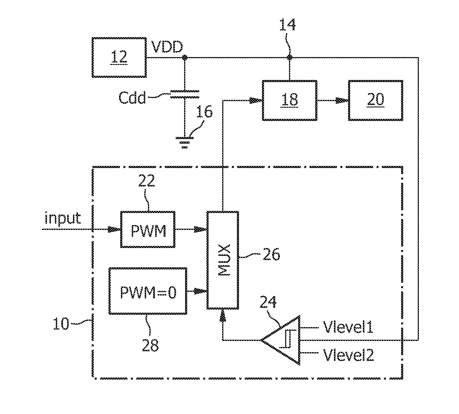
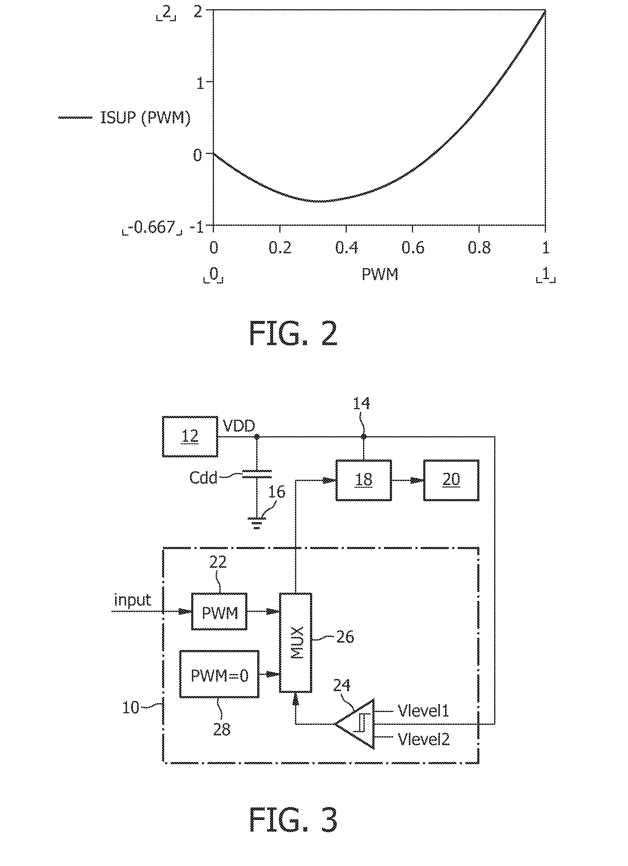
[0034]FIG. 3 shows a block diagram of a circuit using a controller 10 in accordance with the invention and being suitable for performing the method in accordance with the present invention. Besides the controller 10, which will be explained in detail later, the circuit comprises a power supply 12 having a power supply output 14. The power supply 12 is intended to provide at the supply voltage output a constant voltage VDD. Between the power supply output 14 and ground 16 there is provided a decoupling capacitor Cdd. Furthermore, a bridge driver 18 coupled to the power supply output 14 is provided for driving a DC motor 20. The bridge driver 18 is controlled by the controller 10 which comprises means 22 in form of a PWM signal generator 22 for applying a deceleration PWM signal to the bridge driver 18. It should be clear that the PWM signal generator 22 can also be adapted to provide acceleration PWM signals, but such acceleration PWM signals are of lower interest for the present inv...

second embodiment

[0036]FIG. 4 shows a block diagram of a circuit using a controller 10 in accordance with the invention and being also suitable for performing the method in accordance with the present invention. Besides the controller 10, which will be explained in detail below, also the circuit of FIG. 4 comprises a power supply 12 having a power supply output 14. The power supply 12 is intended to provide at the supply voltage output a constant voltage VDD. As illustrated, a load current Iload is drawn from further circuitry not shown in detail. Between the power supply output 14 and ground 16 there is provided a decoupling capacitor Cdd. Again, a bridge driver 18 coupled to the power supply output 14 is provided for driving a DC motor 20. The bridge driver 18 is controlled by the controller 10 which in this case comprises means 22 in form of a PWM signal generator 22 for applying a deceleration PWM signal to the bridge driver 18. Also for the embodiment of FIG. 4 it should be clear that the PWM s...


PUM


Abstract

The invention is directed to a method for controlling a deceleration process of a DC motor (20), wherein the DC motor (20) is driven by a bridge driver (18) coupled to a power supply (12) intended to provide a supply voltage VDD at a power supply output (14), the method comprising the following steps: applying a deceleration PWM signal to the bridge driver (18) for decelerating the DC motor (20), and controlling the bridge driver (18) such that a motor-induced back current is reduced, if the voltage at the power supply output (14) exceeds a first voltage threshold which is higher than VDD. In accordance with the invention the method comprises the following step: if the voltage at the power supply output (14) falls below a second voltage threshold which is lower than the first voltage threshold, terminating controlling the bridge driver (18) such that the motor-induced back current is reduced. The invention is also directed to a controller (10) for controlling a deceleration process of a DC motor (20) which is driven by a bridge driver (18) coupled to a power supply (12) intended to provide a supply voltage VDD at a power supply output (14), the controller (10) comprising: means (22) for applying a deceleration PWM signal to the bridge driver for decelerating the DC motor, and means (24, 26, 28; 24, 30) for controlling the bridge driver (18) such that the motor-induced back current is reduced, if the voltage at the power supply output (14) exceeds a first voltage threshold which is higher than VDD. In accordance with the invention the means for controlling the bridge driver (18) such that the motor-induced back current is reduced are adapted to terminate controlling the bridge driver (18) such that the motor-induced back current is reduced, if the voltage at the power supply output (14) falls below a second voltage threshold which is lower than the first voltage threshold.

Description

FIELD OF THE INVENTION[0001]The present invention relates to a method for controlling a deceleration process of a DC motor, wherein the DC motor is driven by a bridge driver coupled to a power supply intended to provide a supply voltage VDD at a power supply output, the method comprising the following steps: applying a deceleration PWM signal to the bridge driver for decelerating the DC motor, and controlling the bridge driver such that a motor-induced back current is reduced, if the voltage at the power supply output exceeds a first voltage threshold which is higher than VDD.[0002]Furthermore, the invention is directed to a controller for controlling a deceleration process of a DC motor which is driven by a bridge driver coupled to a power supply intended to provide a supply voltage VDD at a power supply output, the controller comprising: means for applying a deceleration PWM signal to the bridge driver for decelerating the DC motor, and means for controlling the bridge driver such...

Claims


Application Information

Patent Timeline
IPC IPC(8): H02P3/14
CPCH02P23/0063H02P23/20
Inventor HOOGZAAD, GIAN
Owner NXP BV
Why Eureka
Try Eureka