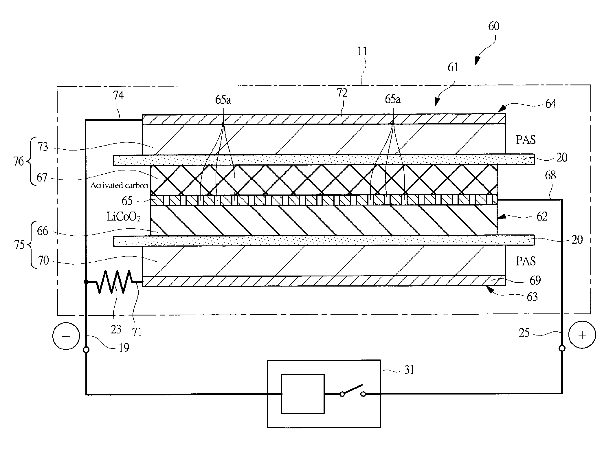
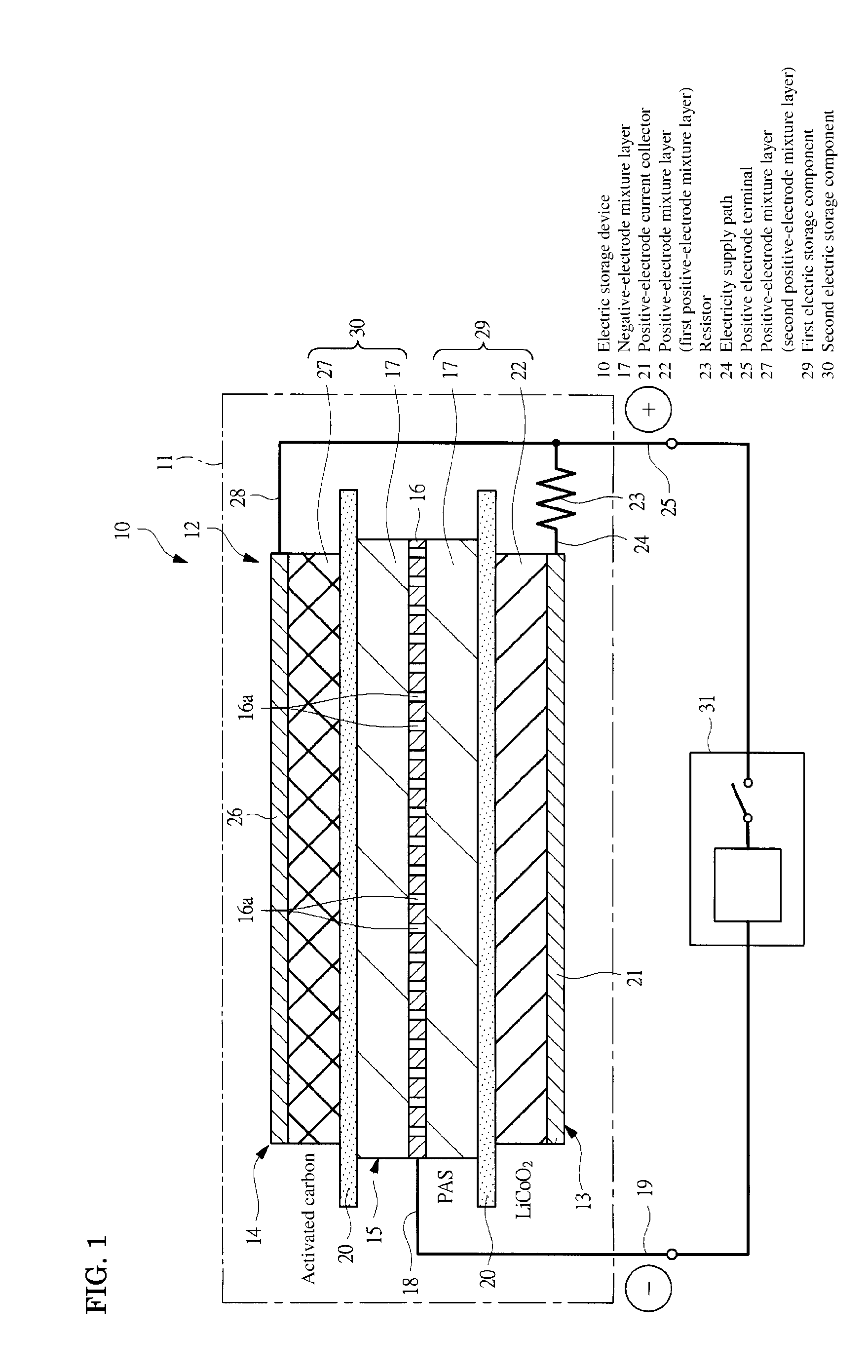
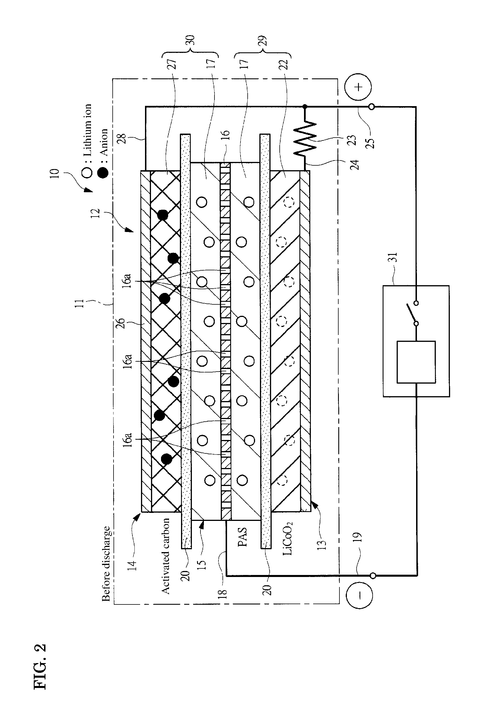
Electric storage device
a technology of electric storage device and electric double layer capacitor, which is applied in the direction of cell components, flat cell grouping, sustainable manufacturing/processing, etc., can solve the problems of low output, high capacity of lithium ion secondary batteries, low capacity, etc., and achieves increased output and capacity of electric storage devices. , the effect of increasing the capacity
- Summary
- Abstract
- Description
- Claims
- Application Information
AI Technical Summary
Benefits of technology
Problems solved by technology
Method used
Image

Examples
example 1
[Fabrication of Negative Electrode 1]
[0101]A phenolic resin molded plate with a thickness of 0.5 mm was put into a Siliconit electric furnace and heat-treated under a nitrogen atmosphere at a rate of 50° C. / hour till temperature reached 500° C., and further heat-treated at the rate of 10° C. / hour till temperature reached 700° C., whereby a PAS plate was synthesized. The PAS plate thus synthesized was pulverized with a disc mill into PAS powders. The PAS powders had a H / C ratio of 0.17.
[0102]Then, 100 parts by weight of the above PAS powder and a solution prepared by dissolving 10 parts by weight of polyvinylidene fluoride powder in 80 parts by weight of N-methyl pyrrolidone were sufficiently mixed to prepare a slurry 1 for the negative electrode. The slurry 1 for the negative electrode was coated uniformly over both surfaces of a copper expanded metal (manufactured by Nippon Metal Industry Co., Ltd.) having a thickness of 32 μm (porosity of 50%) by a die coater. The slurry 1 for the...
example 2
[Fabrication of Cell 3]
[0117]Four cells 3 were assembled in the same manner as in the Example 1, except that ten sheets of non-woven fabric made of polyethylene with a thickness of 35 μm, which were used as the separator, were arranged between the positive electrode 1 and the negative electrode 2. Specifically, ten separators were superimposed between the positive electrode 1 and the negative electrode 1, while one separator was arranged between the positive electrode 2 and the negative electrode 1. The amount of the metal lithium located in each cell 3 was equivalent to 380 mAh / g per negative-electrode active material weight.
[Initial Evaluation of Cell 3]
[0118]The thus assembled cells 3 were left for 30 days, and one cell of four cells 3 was disassembled. It was confirmed that no metal lithium remained. From this fact, it was considered that the amount of lithium ion equivalent to 380 mAh / g per negative-electrode active material weight was pre-doped.
[Characteristic Evaluation of Ce...
example 3
[Evaluation of Overdischarge Characteristic of Cell 1]
[0123]The cell 1 was charged at a constant current of 100 mA till the cell voltage reached 4.0 V, and then the cell 1 was charged by applying a constant voltage of 4.0 V. This constant-current constant-voltage charging method was performed for 6 hours. Then, the cell was discharged at a constant current of 100 mA till the cell voltage reached 0 V. The cycle of the charging operation (100 mA charge) to 4.0 V and the discharging operation (100 mA discharge) to 0 V was repeated, and when the cycle was repeated 10 times, no trouble such as swelling of the cell was not observed.
PUM
| Property | Measurement | Unit |
|---|---|---|
| voltage | aaaaa | aaaaa |
| voltage | aaaaa | aaaaa |
| current | aaaaa | aaaaa |
Abstract
Description
Claims
Application Information
 - R&D Engineer
- R&D Manager
- IP Professional
- Industry Leading Data Capabilities
- Powerful AI technology
- Patent DNA Extraction
Browse by: Latest US Patents, China's latest patents, Technical Efficacy Thesaurus, Application Domain, Technology Topic.
© 2024 PatSnap. All rights reserved.Legal|Privacy policy|Modern Slavery Act Transparency Statement|Sitemap