Dichroic beamsplitter for high energy laser diagnostics

a laser diagnostic and dichroic beam technology, applied in the field of laser alignment techniques, can solve problems such as difficulty in building such a system, and achieve the effects of wide dynamic range, high signal-to-noise ratio, and optimized laser performance characteristics

Inactive Publication Date: 2011-08-30
LAWRENCE LIVERMORE NAT SECURITY LLC
View PDF8 Cites 4 Cited by
  • Summary
  • Abstract
  • Description
  • Claims
  • Application Information

AI Technical Summary

Problems solved by technology

It can be difficult to build such a system that can both accommodate the high power laser and transmit enough of the low power probe laser to be able to calibrate the system with a high signal to noise ratio.

Method used


Image

  • Dichroic beamsplitter for high energy laser diagnostics
  • Dichroic beamsplitter for high energy laser diagnostics
  • Dichroic beamsplitter for high energy laser diagnostics

Examples


Embodiment Construction

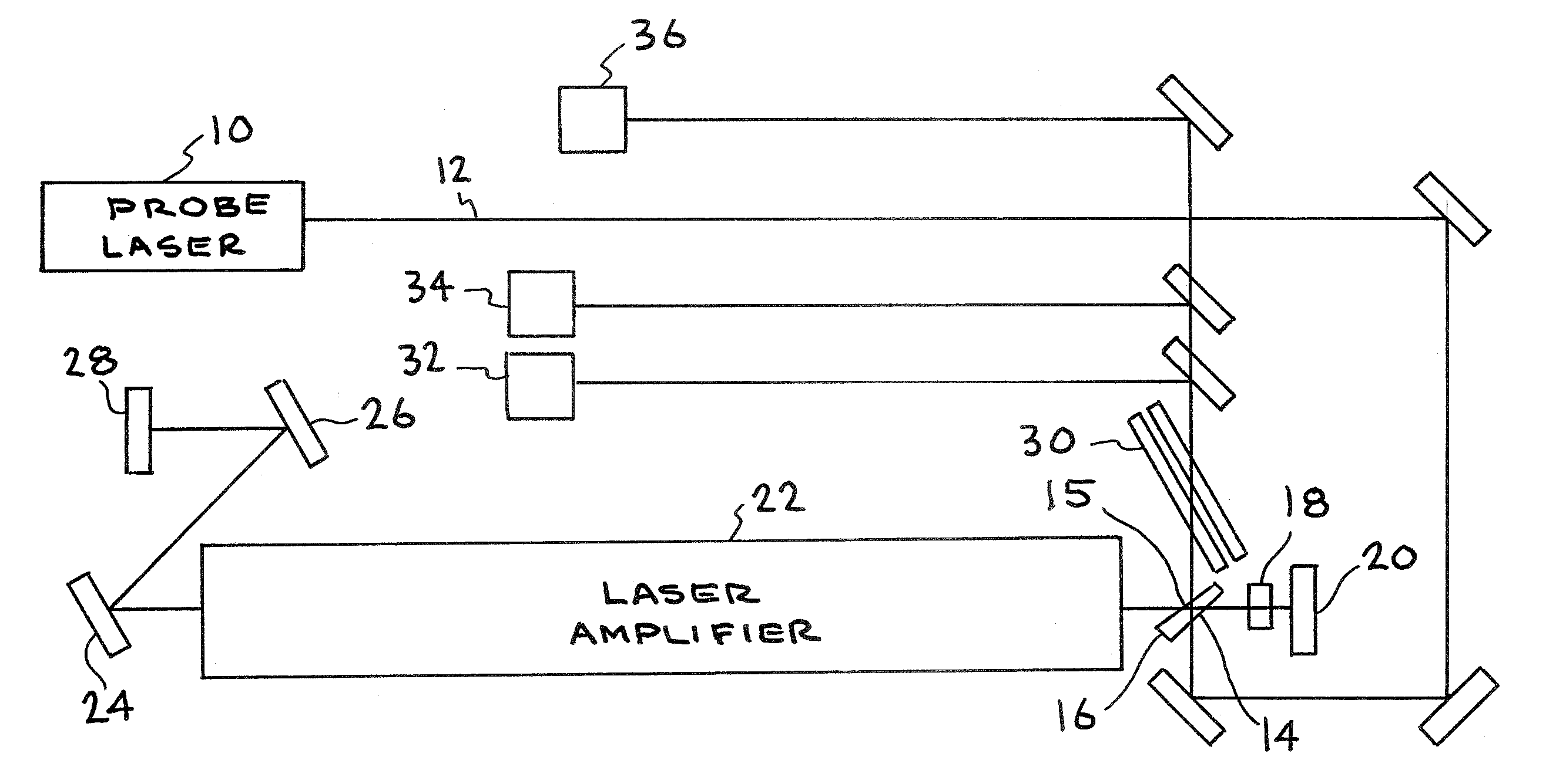
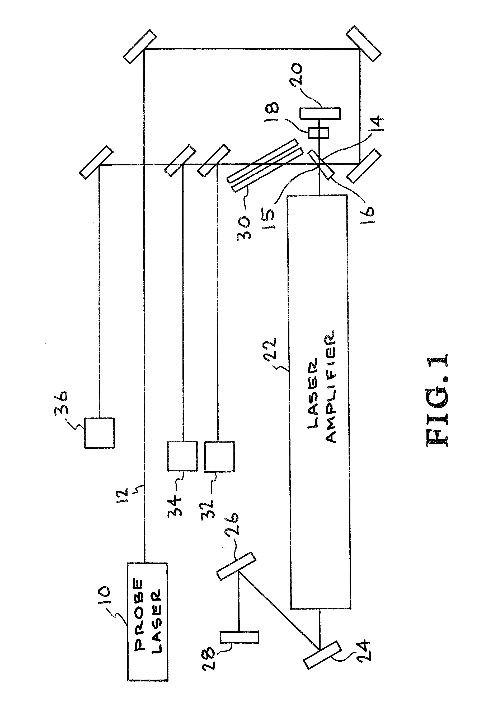
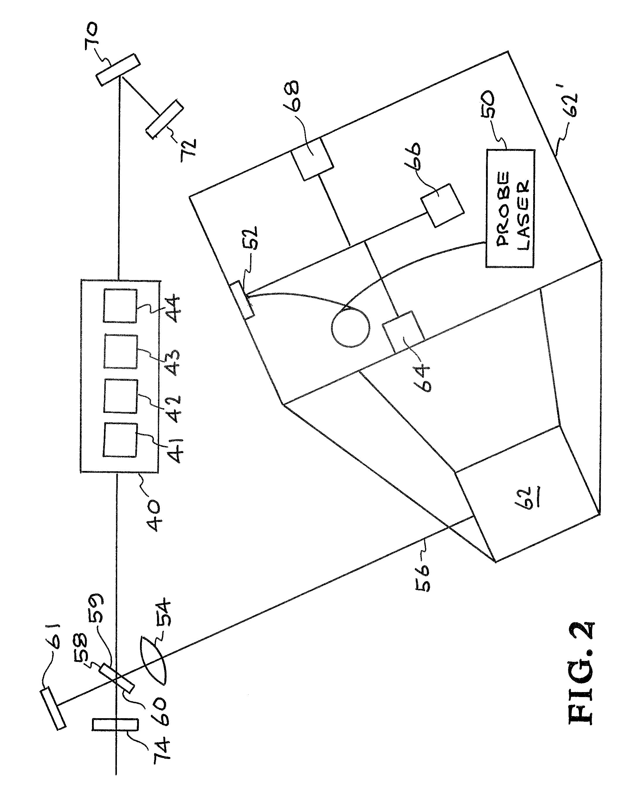
[0016]The present invention includes designs for a beam splitter that can be used for the alignment of a high-power laser; especially one that needs active wavefront control. The beam splitter can comprise an optic that has two flat surfaces that are not parallel by a small wedge angle. Each surface is coated with a different optical coating.

[0017]The angle of the wedge should be small enough not to introduce too much astigmatism into the optical path and yet large enough so that reflections from one of the surfaces can be rejected while reflections from the other surface can be collected in the diagnostics. In one embodiment, the wedge angle is about half of a degree.

[0018]The beam splitter is designed for two wavelengths. The high-power laser is designed to run at a single wavelength, say l0. The probe laser is chosen to run at a single yet different wavelength, say l1. The two wavelengths are chosen to be similar enough such that l0-l10. With this condition satisfied, the propaga...


PUM


Abstract

Wavefront control techniques are provided for the alignment and performance optimization of optical devices. A Shack-Hartmann wavefront sensor can be used to measure the wavefront distortion and a control system generates feedback error signal to optics inside the device to correct the wavefront. The system can be calibrated with a low-average-power probe laser. An optical element is provided to couple the optical device to a diagnostic / control package in a way that optimizes both the output power of the optical device and the coupling of the probe light into the diagnostics.

Description

[0001]This application claims priority to U.S. Provisional Application No. 61 / 128,666, titled “Dichroic Beamsplitter for High Energy Laser Diagnostics,” filed May 23, 2008, incorporated herein by reference.[0002]The United States Government has rights in this invention pursuant to Contract No. DE-AC52-07NA27344 between the United States Department of Energy and Lawrence Livermore National Security, LLC.BACKGROUND OF THE INVENTION[0003]1. Field of the Invention[0004]The present invention relates to laser alignment techniques, and more specifically, it relates to the control of the wavefront of a laser in real time.[0005]2. Description of Related Art[0006]All lasers, including high-power, solid-state lasers, need a means of alignment. For low-power, continuous wave (cw) lasers, this may mean a trivial tilting of mirrors while the laser is in operation. For high-power lasers, especially pulsed, high-power lasers, it is not, in general, practical to align the system, at least initially,...

Claims


Application Information

Patent Timeline
Patent Type & Authority Patents(United States)
IPC IPC(8): G01B11/26
CPCG01J1/4257G02B26/001G02B27/1006G02B27/108G02B27/14G02B27/141G02B27/145H01S3/08059H01S3/086G01J9/00H01S3/0014H01S3/0941H01S3/1307H01S3/1611H01S3/1643H01S3/2316
Inventor LAFORTUNE, KAI NHURD, RANDALLFOCHS, SCOTT NROTTER, MARK DHACKEL, LLOYD
Owner LAWRENCE LIVERMORE NAT SECURITY LLC
Why Eureka
Try Eureka