Cleaning implement

a technology of cleaning implements and mop heads, which is applied in the field of cleaning implements, can solve the problems of difficult operation of mops and difficulty in expulsion of liquid from mops during wringing operations, and achieve the effect of reducing slippage and increasing the twisting of mop heads

Active Publication Date: 2011-09-06
CARL FREUDENBERG KG +1
View PDF101 Cites 34 Cited by
  • Summary
  • Abstract
  • Description
  • Claims
  • Application Information

AI Technical Summary

Benefits of technology

[0007]According to another aspect of the invention, the wringing sleeve comprises a major volute, which includes a generally helicoid surface. The volute assists the sleeve in twisting the mop strings or strips about the shaft to thereby assist in expelling liquid. The volute also includes two opposing fins that run at least a portion of the length of the volute and define a gap therebetween along at least a portion of the length of the fins. When the sleeve is lowered over the mop, at least one strip or string of the mop may be trapped between the fins of the sleeve. The grabbing of the mop strips or strings by the major volute helps ensure that as the sleeve is rotated relative to the shaft, the twisting of the mop is increased due to reduced slippage between the sleeve and the mop.

Problems solved by technology

A principal drawback with many known sleeve-type mops is that it is difficult to expel liquid from the mop during the wringing operation.
Another drawback is that such mops can be difficult to operate.

Method used


Image

  • Cleaning implement
  • Cleaning implement
  • Cleaning implement

Examples


Embodiment Construction

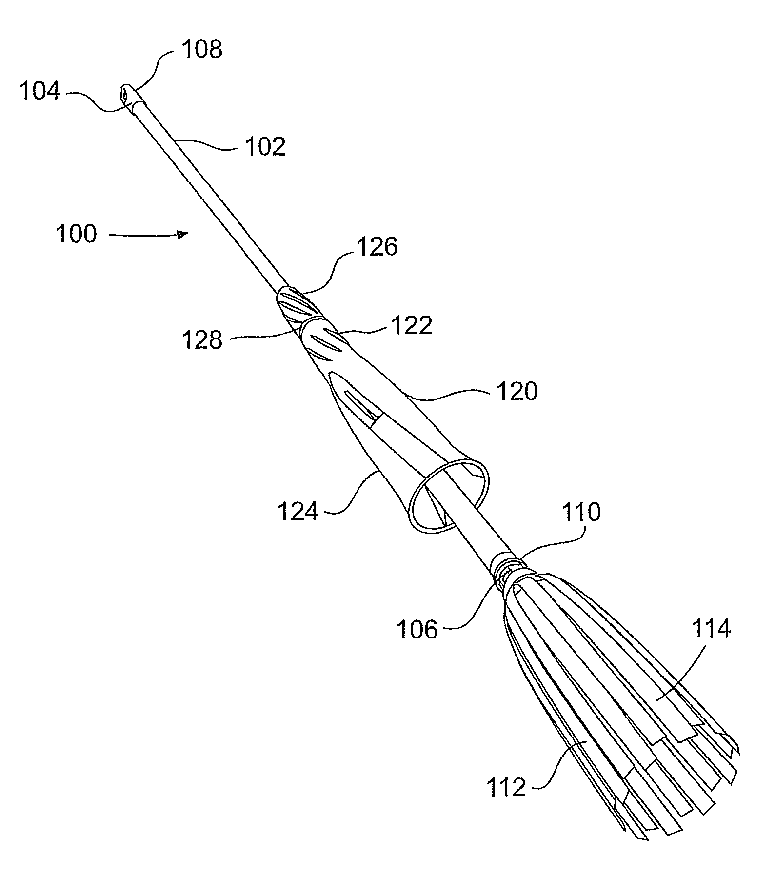
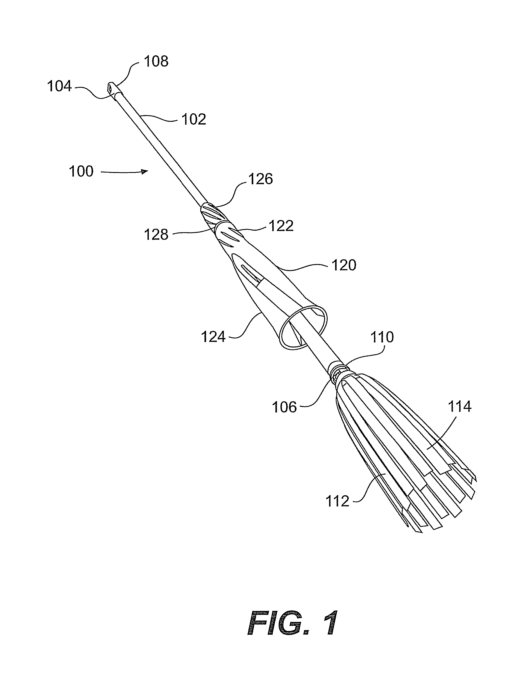
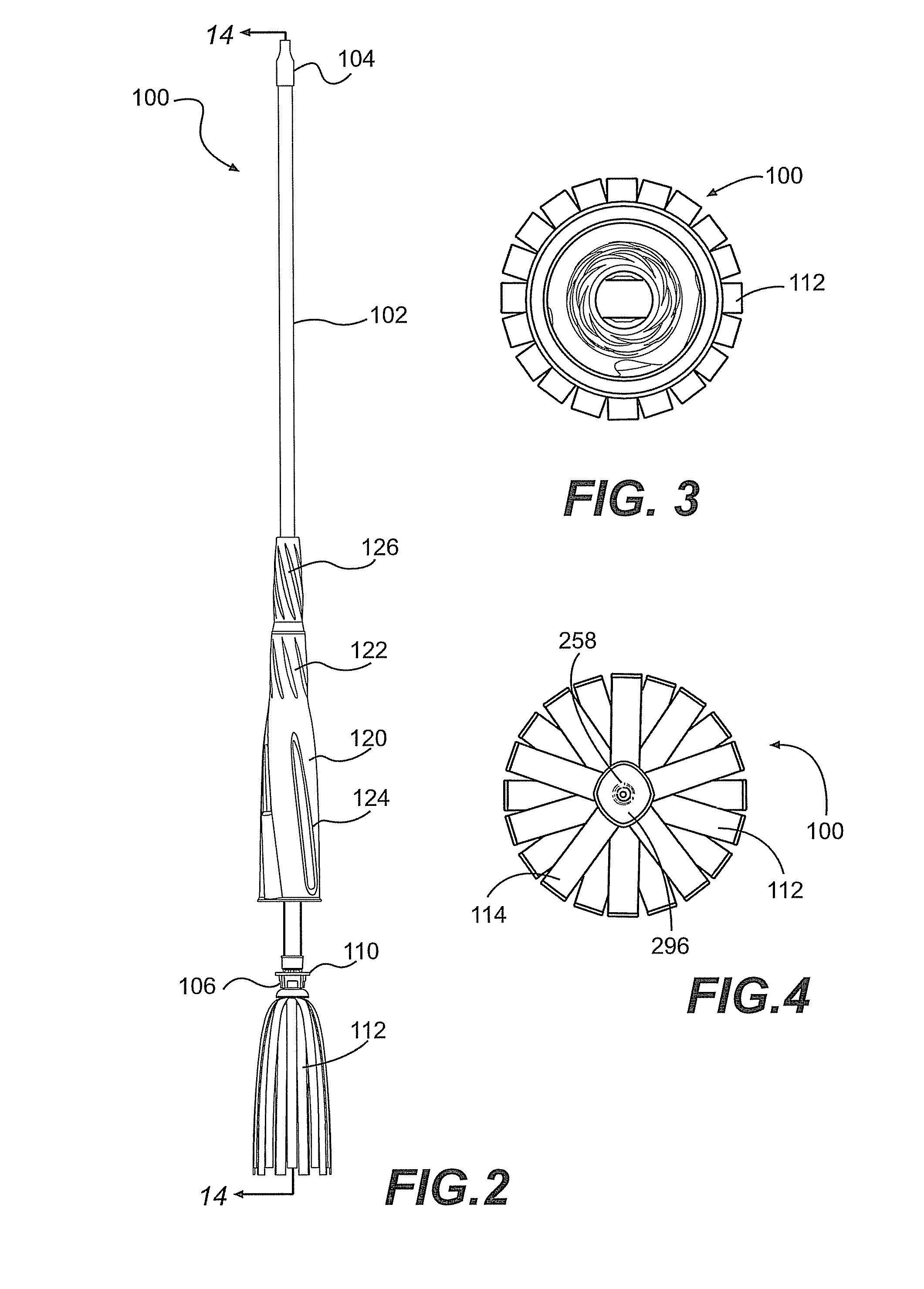
[0042]Now referring to the drawings, wherein like reference numbers refer to like features, there is illustrated in FIG. 1 an exemplary cleaning implement 100 according to the invention. The cleaning implement 100 comprises a shaft 102 having an operator end 104 and a mopping end 106. A hanger cap 108 is disposed at the operator end of the shaft 102, and a mop assembly 110 that includes a mop 112 is disposed at the mopping end 106. The mop 112 may be made of any suitable liquid absorbent material such as fabric strips, strings, or the like. The mop may be composed of composite fabric strips 114.

[0043]Referring to FIGS. 1 and 2, the cleaning implement 100 further includes a wringing assembly or wringer 120, the wringer 120 including a wringer handle 122 and a wringing sleeve 124, the handle 122 being disposed relatively proximal the operator end 104 of the shaft 102. The wringer 120 is axially moveable with respect to the shaft 102 over a range of travel between a fully retracted pos...


PUM


Abstract

A cleaning implement that includes a shaft, a mop disposed on one end of the shaft, a wringer, and a fixed grip. The wringer includes a wringing sleeve and a wringer handle. The wringer is movable over a range of travel between a mopping position and a range of wringing positions, in which wringing positions the wringing sleeve covers and compresses at least a portion of the mop to thereby expel liquid from the mop. The wringer is rotatable relative to the shaft through at least a portion of the axial range of travel. The wringer further comprises at least one volute wherein the volute defines a semi-enclosed area inside the wringer, the semi-enclosed area configured to receive a portion of the mop through a gap defined in the volute. The volute includes a first fin and a second fin that define the gap therebetween.

Description

CROSS-REFERENCE TO RELATED APPLICATIONS[0001]This patent application claims the benefit of U.S. Provisional Patent Application No. 60 / 810,405, filed Jun. 1, 2006, and U.S. Provisional Application No. 60 / 905,940, filed Mar. 9, 2007, which are incorporated by reference.FIELD OF THE INVENTION[0002]The present invention relates generally to cleaning implements, and more particularly to a cleaning implement with a wringer.BACKGROUND OF THE INVENTION[0003]A wide variety of cleaning implements are known in the art, and the prior art has provided numerous sweepers, brooms, mops, and the like. In recent years, one trend in the cleaning implement industry has been towards “self-wringing” cleaning implements or mops, the term “self-wringing” signifying that water or cleaning fluids may be wrung from the cleaning implement without the aid of a separate wringer bucket or other wringing device. One such type of “self wringing” cleaning element is the sleeve-type mop. A principal drawback with man...

Claims


Application Information

Patent Timeline
Patent Type & Authority Patents(United States)
IPC IPC(8): A47L13/14A47L13/20A47L13/50
CPCA47L13/142
Inventor LESLEY, PAUL M.
Owner CARL FREUDENBERG KG
Why Eureka
Try Eureka