

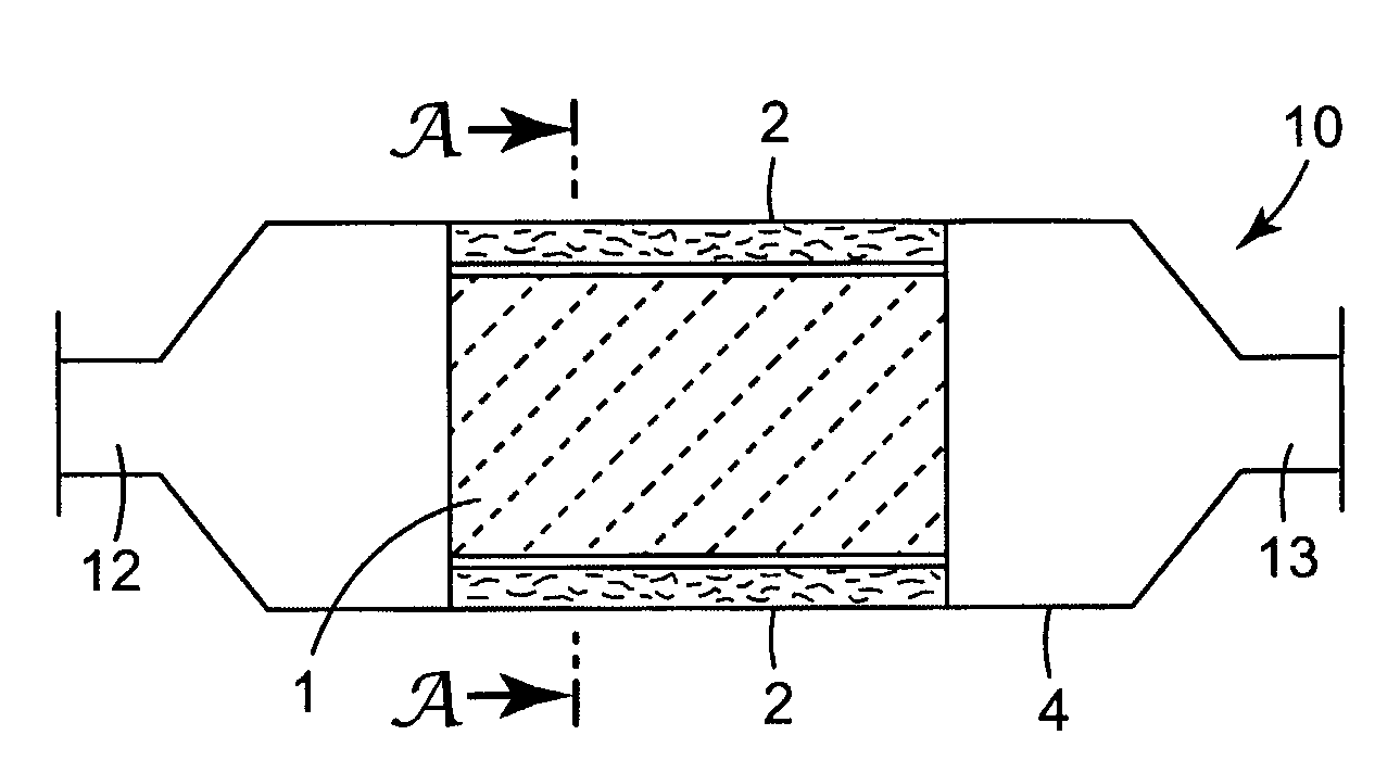
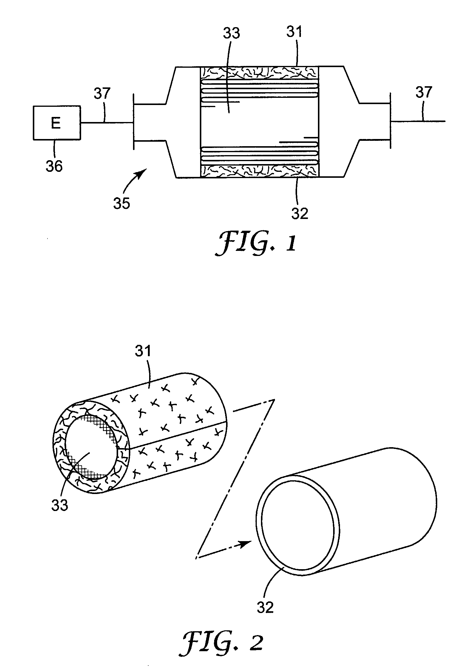
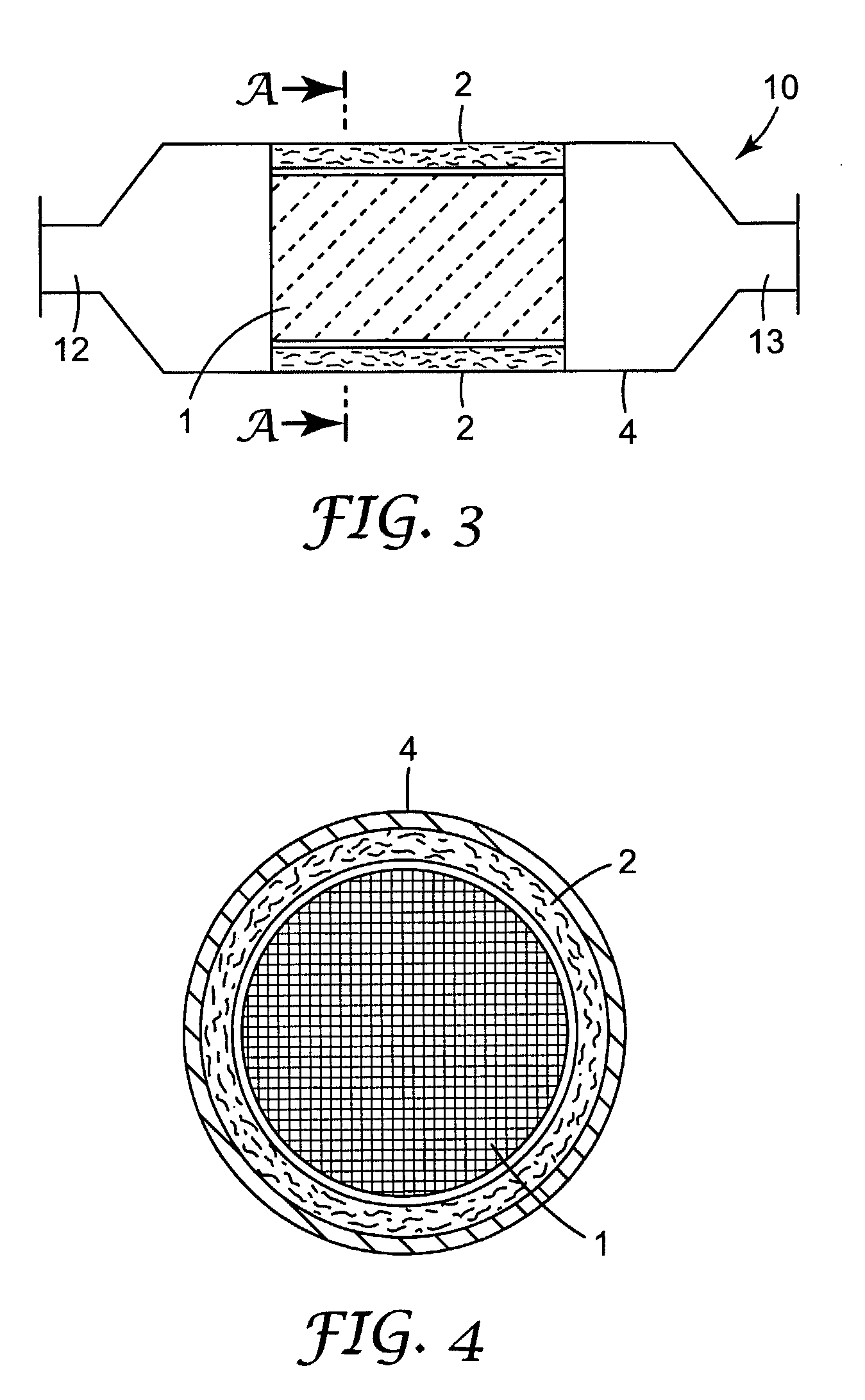
Pollution Control Element Mounting System and Pollution Control Device
a technology of mounting system and pollution control element, which is applied in the direction of machines/engines, filtration separation, separation processes, etc., can solve the problems of excessive drop in force, and fracture of ceramic fiber and other inorganic fiber used in the mounting system, so as to improve the retaining force of the pollution control element, increase the pressure generated by the mounting system, and increase the degree of compression of the mounting system
- Summary
- Abstract
- Description
- Claims
- Application Information
AI Technical Summary
Benefits of technology
Problems solved by technology
Method used
Image

Examples
examples
[0071]Subsequently, the invention will be explained with reference to examples thereof. Incidentally, the invention is not of course limited by these examples.
[0072]An alumina silica fiber (product of Mitsubishi Kagaku Sanshi) consisting of 72 wt % of alumina and 28 wt % of silica was first prepared and 88 wt % of this fiber and 12 wt % of acryl type latex (“Nippol LX-816”, product of Nippon Zeon K. K.) were mixed to give first slurry. When this slurry was prepared, the water content was adjusted so that a solid concentration became 5 wt %. Next, the first slurry was dehydrated and shaped into a sheet on a mesh to give a sheet-like mold. The mold was then compressed by use of pressure rollers to attain a high density. Next, the resulting high density mold was dried at 130° C. for 20 minutes by use of heating rollers to give a non-expandable mat. A mean surface density of this non-expandable mat was about 1,200 g / m2. Incidentally, this non-expandable mat was used also as a Control Sa...
PUM
| Property | Measurement | Unit |
|---|---|---|
| packing density | aaaaa | aaaaa |
| temperature | aaaaa | aaaaa |
| surface pressure | aaaaa | aaaaa |
Abstract
Description
Claims
Application Information