Engine arrangement

a technology of engine and arrangement, applied in the direction of machines/engines, liquid fuel engines, transportation and packaging, etc., can solve the problems of engine complexity, engine damage to subsequent parts and stages, production costs, etc., and achieve the effect of reducing the disruption of the core flow

Inactive Publication Date: 2011-09-06
ROLLS ROYCE PLC
View PDF19 Cites 14 Cited by
  • Summary
  • Abstract
  • Description
  • Claims
  • Application Information

AI Technical Summary

Benefits of technology

[0007]In accordance with aspects of the present invention there is provided an engine arrangement for a component subject to icing in use, the arrangement comprises a manifold that includes a hole to create a jet having an exit angle toward a component subject to icing, the jet of hot gas is entrained in use in a core flow passing through the main flow path before washing over a desired incident area of the component, the exit angle and / or spacing between the jet and the component are determined to reduce disruption of the core flow and / or provide the desired incident area upon the component and / or use the minimum amount of hot air.

Problems solved by technology

In such circumstances ice may build up on these guide vanes, which will then eventually be shed potentially causing damage to subsequent parts and stages of the engine 10.
Unfortunately hollow components increase engine complexity and therefore production costs and so result in extended manufacturing timescales.
Furthermore, components which move or rotate add additional complexity and potential leakage through the need to provide hot air flow through a rotating spindle to the component for heating to avoid icing on that component.

Method used


Image

  • Engine arrangement
  • Engine arrangement
  • Engine arrangement

Examples


Embodiment Construction

.

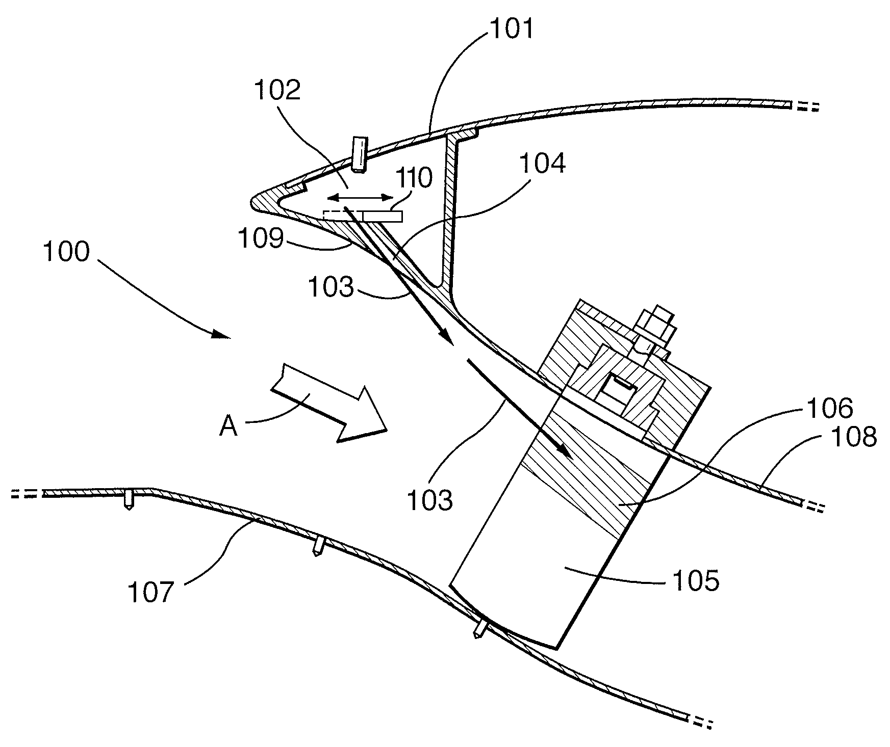
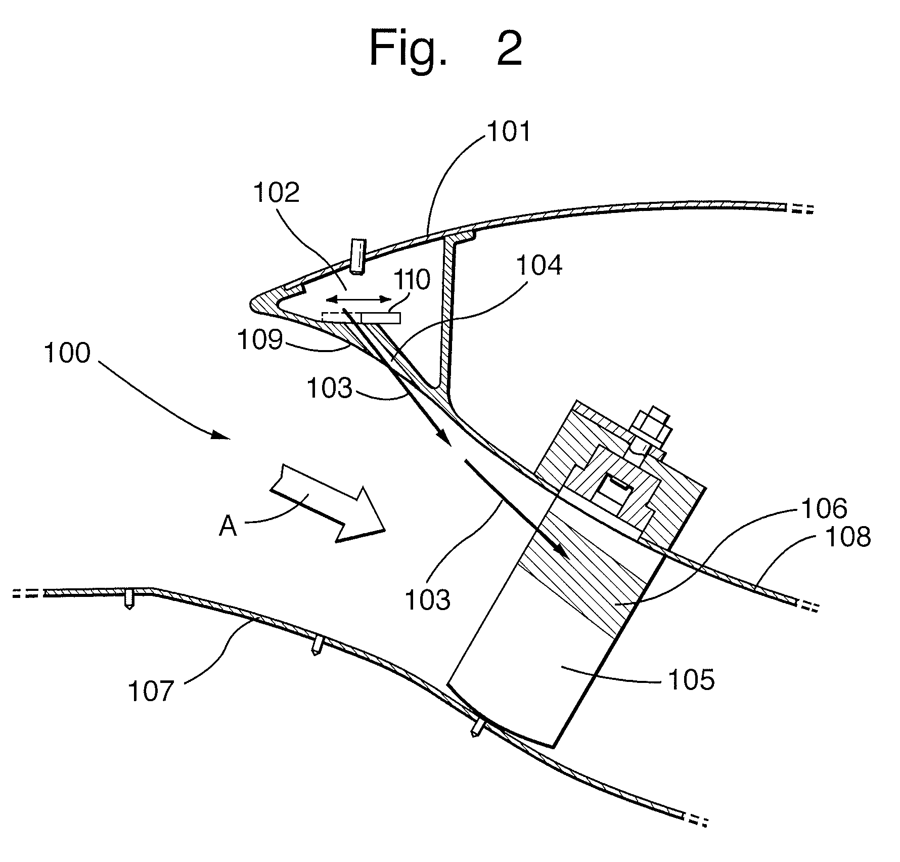
[0017]An embodiment in accordance with aspects of the present invention will now be described by way of example only and with reference to the accompanying drawing, FIG. 2 illustrating a part-schematic cross-section of an engine arrangement.

[0018]As indicated above, certain components in engines such as gas turbine engines may be subject to icing as a result of their position within a flow path through the engine. These components may take the form of vanes or struts within ducting which forms the flow path. This icing will build upon the component until shed when lumps of ice may create problems in subsequent parts of the engine. Clearly and ideally ice should be limited from forming at all but this will generally be impractical. It will be understood that overall engine efficiency must be considered and therefore a balance struck between conflicting objectives for de-icing or preventing icing with as little energy as possible but without disruption or erosion of the normal core f...


PUM


Abstract

An engine arrangement for a component subject to icing. The arrangement comprising a manifold as part of a flow path incident upon a heated component. The manifold including holes to create jets having an exit angle toward the component subject to icing. The jets of hot gas are entrained in a core flow passing through the main flow path before washing over a desired incident area of the component. The exit angle and spacing between the jet and the component are determined to reduce disruption of the core flow and / or provide the desired incident area on the component and / or use the minimum amount of hot air.

Description

CROSS-REFERENCE TO RELATED APPLICATION[0001]This application is entitled to the benefit of British Patent Application No. GB 0621001.7 filed on Oct. 21, 2006.FIELD OF THE INVENTION[0002]The present invention relates to engine arrangements and more particularly to gas turbine arrangements including components such as vanes and struts which may be subject to icing.BACKGROUND OF THE INVENTION[0003]Referring to FIG. 1, a gas turbine engine is generally indicated at 10 and comprises, in axial flow series, an air intake 11, a propulsive fan 12, an intermediate pressure compressor 13, a high pressure compressor 14, a combustor 15, a turbine arrangement comprising a high pressure turbine 16, an intermediate pressure turbine 17 and a low pressure turbine 18, and an exhaust nozzle 19.[0004]The gas turbine engine 10 operates in a conventional manner so that air entering the intake 11 is accelerated by the fan 12 which produce two air flows: a first air flow into the intermediate pressure compr...

Claims


Application Information

Patent Timeline
Patent Type & Authority Patents(United States)
IPC IPC(8): F02G3/00
CPCF02C7/047F02K3/06F04D29/705F04D27/0238F04D29/584Y10T137/0536B64D15/04
Inventor LOCKWOOD, CLIVE
Owner ROLLS ROYCE PLC
Why Eureka
Try Eureka