System and device for measuring and analyzing forces applied by a cyclist on a pedal of a bicycle

a technology for analyzing forces and bicycles, applied in the field of bicycle pedals, can solve the problems of reducing the efficiency of cyclists, limited use in laboratories, and extensive calibration and complicated equipment, and achieve the effect of improving the pedaling technique of cyclists

Active Publication Date: 2011-09-06
GARMIN
View PDF62 Cites 96 Cited by
  • Summary
  • Abstract
  • Description
  • Claims
  • Application Information

AI Technical Summary

Benefits of technology

[0014]In accordance with some embodiments, a system for improving a pedaling technique of a cyclist is also provided. The system includes a sensor provided in a pedal spindle of a pedal, the sensor determining forces exerted by the cyclist on the pedal, a storage medium and a processor coupled to the sensor, the processor executing instructions stored in the storage medium for analyzing the determined forces to provide information related to the pedaling of the cyclist, a display coupled to the sensor, the display providing the information in real time to the cyclist.

Problems solved by technology

Forces exerted by the cyclist in any other direction are considered wasted forces, which reduce the cyclist's efficiency.
The previous devices and systems, however, have required extensive calibration and complicated equipment, and therefore have been limited to use in the laboratory.
Moreover, the Reiser system also requires complex external electronics, including a portable computer, in order to provide data, thus making the system impractical for immediate analysis by a cyclist while riding.
The prior art pedals, however, often require extensive external electronics for processing, making them unsuitable for use outside of a laboratory.
In addition, those systems and devices that have been designed for portability often require specialized equipment, are susceptible to damage from external environmental factors, or produce results which are very noisy, and thus are unable to provide accurate, useful results to the cyclist.

Method used


Image

  • System and device for measuring and analyzing forces applied by a cyclist on a pedal of a bicycle
  • System and device for measuring and analyzing forces applied by a cyclist on a pedal of a bicycle
  • System and device for measuring and analyzing forces applied by a cyclist on a pedal of a bicycle

Examples


Embodiment Construction

[0029]Reference will now be made in detail to the disclosed embodiments which are illustrated in the accompanying drawings. Wherever possible, the same reference numbers will be used throughout the drawings to refer to the same or like parts.

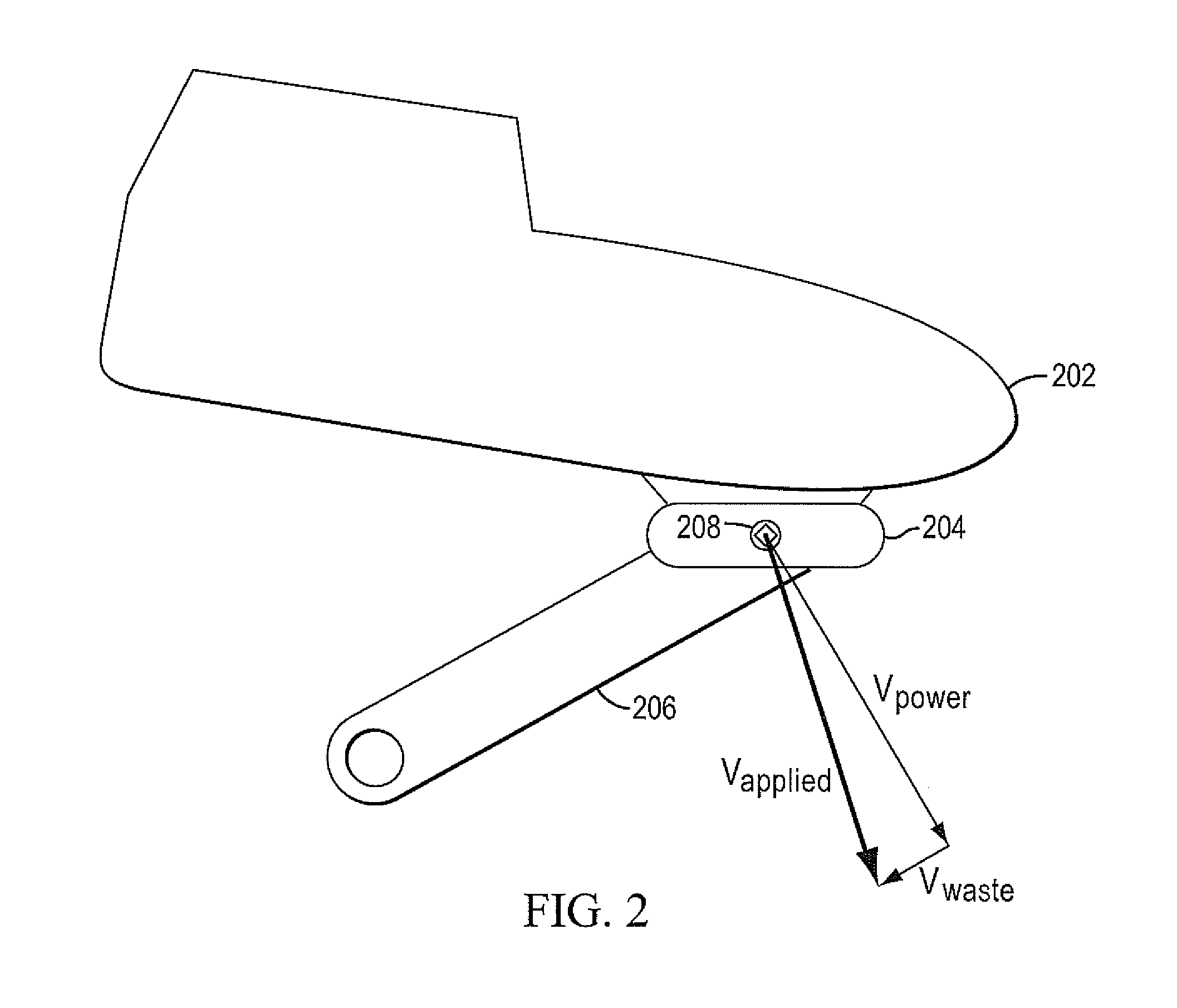
[0030]Embodiments disclosed herein are related to devices and systems which may be used to measure properties of cyclists as they pedal their bicycles. Such properties include the applied and wasted forces or power applied by a cyclist on a pedal, the cyclist's cadence, the cyclist's heart rate, the cyclist's pedaling efficiency, and the speed, inclination, slope, and grade of the bicycle. In particular, embodiments disclosed herein are related to a sensor or device that is able to measure these properties. The sensor or device may be affixed or mounted on a part of the cyclist, such as the cyclist's shoe, or may be mounted on or in the pedal. According to some embodiments, the sensor or device may be mounted in the pedal spindle. A pedal spindl...


PUM


Abstract

According to some embodiments, a sensor device for determining forces exerted by a cyclist on a pedal of a bicycle is provided. The sensor device includes a plurality of sensors coupled to a substrate, and wiring coupled to the sensors and the substrate, wherein the sensors, the substrate, and the wiring are housed inside a pedal spindle coupled to the pedal. The sensor device may also be used in a system for improving a pedaling technique of a cyclist.

Description

RELATED APPLICATIONS[0001]This application claims priority to U.S. Provisional Application No. 61 / 084,603, filed on Jul. 29, 2008, and U.S. Provisional Application No. 61 / 154,671 filed on Feb. 23, 2009. The contents of these applications are hereby incorporated by reference in their entirety.TECHNICAL FIELD[0002]The present disclosure is related to a device for measuring and analyzing forces applied by a cyclist on a pedal. The device may be used in a system for presenting the analysis of the applied forces to the cyclist or a coach to assist in training and maximizing performance.BACKGROUND[0003]A cyclist achieves optimal pedaling efficiency when there is little to no wasted force exerted on a pedal. This occurs when force is exerted on the pedal in a direction tangential to the arc of pedal travel in the direction of rotation of the cycle's crank. Forces exerted by the cyclist in any other direction are considered wasted forces, which reduce the cyclist's efficiency. By actively a...

Claims


Application Information

Patent Timeline
Patent Type & Authority Patents(United States)
IPC IPC(8): A61B5/22
CPCG01L3/242G01L5/225Y10T74/2164B62J45/411B62M3/08B62J45/421
Inventor O'NEILL, GEORGE DAVIDFOY, CLARK FARRELLCLARK, TIMOTHY S.GAGNON, PATRICE
Owner GARMIN
Why Eureka
Try Eureka