Variable valve opening property internal combustion engine

a technology of variable valve opening and internal combustion engine, which is applied in the direction of valve details, valve arrangements, valve drives, etc., can solve the problems of preventing the efficient transmission of springs, restricting the positioning of springs,

Inactive Publication Date: 2011-09-06
HONDA MOTOR CO LTD
View PDF5 Cites 4 Cited by
  • Summary
  • Abstract
  • Description
  • Claims
  • Application Information

AI Technical Summary

Benefits of technology

[0007]In view of such problems of the prior art, a primary object of the present invention is to provide a variable valve opening property internal combustion engine that can prevent any uncontrolled movement of a key member of a valve opening property varying mechanism such as a link member under all conditions.
[0008]A second object of the present invention is to provide a variable valve opening property internal combustion engine that includes a spring member for urging a key member of a valve opening property varying mechanism to an associated member of a valve actuating mechanism, and is capable of transmitting the spring force of the spring member in an efficient manner irrespective of the position of the key member.
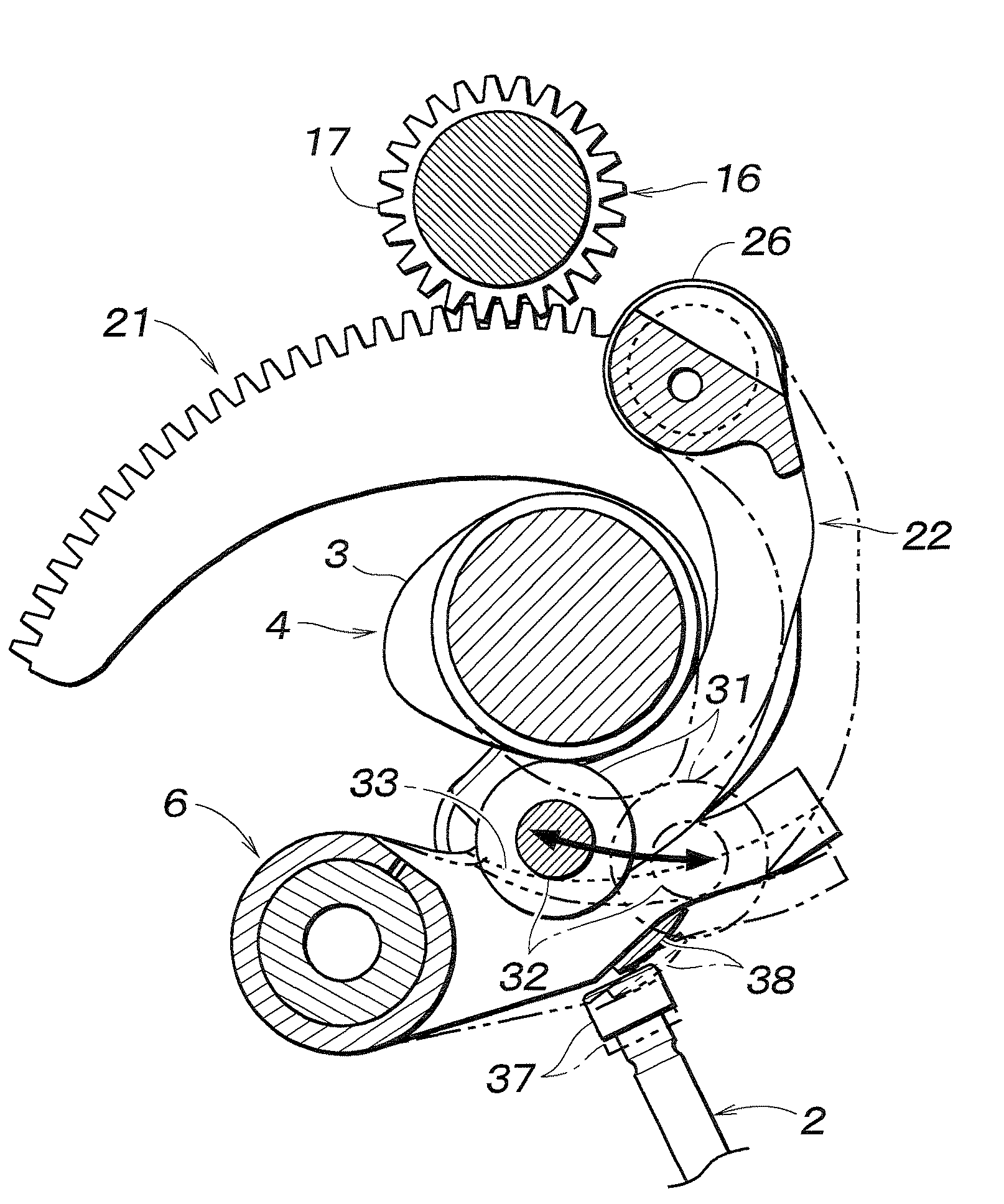
[0010]Thus, the roller link can be biased toward the cam, and the jumping, bouncing and other uncontrolled movement of the roller link can be avoided. In particular, if the pressure surface engages a spring engaging part of the roller link which typically consists of a cam roller, and extends over an entire range of movement of the spring engaging part of the roller link, an uncontrolled movement of the roller link can be avoided at all times. Preferably, the spring device comprises at least a pair of compression springs arranged along direction of a movement of the spring engaging part of the roller link so that the springs may be prevented from tilting as they apply a spring force to the spring engaging part.
[0011]According to a preferred embodiment of the present invention, the pressure surface is contoured such that an angle between a trajectory of the guided motion of the spring engaging part and a direction of a pressure applied by the pressure surface onto the spring engaging part may be minimized. Most preferably, the pressure surface is given with a varying inclination along the trajectory of the movement of the spring engaging part such that an angle between a trajectory of the guided motion of the spring engaging part and a direction of a pressure applied by the pressure surface onto the spring engaging part may be minimized. Thereby, the spring force may be applied to the spring engaging part in an efficient manner over the entire operating range of the valve opening property varying mechanism, and the need for an unduly large and strong spring device can be avoided.

Problems solved by technology

However, the presence of the link mechanism required for varying the valve opening property necessitates a complication of the valve actuating mechanism, and this imposes a restriction on the positioning of the spring.
This in turn prevents the efficient transmission of the spring force to the part where the spring force is needed, Consequently, the spring is required to produce an unduly large spring force in order to provide a required spring force under all conditions.

Method used


Image

  • Variable valve opening property internal combustion engine
  • Variable valve opening property internal combustion engine
  • Variable valve opening property internal combustion engine

Examples


second embodiment

[0044]In the second embodiment illustrated in FIGS. 7a and 7b, the pressure surface 62 of the spring retainer 61 consists of a simple single plane which is perpendicular to the axial lines of the coil springs 42 and 43, and extends from one end 61a to the other 61b. Therefore, the line of action of the spring force Fspg of the coil springs 42 and 43 acting upon the cam roller 31 via the spring retainer 62 is always in parallel with the axial lines of the coil springs 42 and 43.

[0045]In the maximum link angle position (large lift) (with a link angle of 60 degrees, for instance), the first embodiment of the present invention illustrated in FIG. 6b is no different from the second embodiment illustrated in FIG. 7b. However, in the zero link angle position (small lift), there is a significant difference between the two embodiments of the present invention illustrated in FIG. 6a and FIG. 7a, respectively. The angle between the line of action of the pressure surface and the axial lines of ...

first embodiment

[0048]In the first embodiment, the two coil springs 42 and 43 are identical to each other, but may also differ from each other. For instance, the coil spring 42 on the low lift side 44a may be made of thicker coil wire or is otherwise configured to produce a greater spring force than the other so that the undesired tilting of the spring retainer 44 may be avoided.

[0049]In the first embodiment illustrated in FIGS. 6a and 6b, the curvature of the pressure surface 47 of the spring retainer 44 was determined in such a manner that the angle between the line of action of the contact force of the cam roller 31 and the tangential direction of the cam roller 31 around the center of rotation of the roller link 22 (or the force required to turn the roller link 22 around the center of rotation) is reduced to a small value. However, it is also possible to coincide the direction of the line of action of the contact force of the cam roller 31 and the tangential direction of the cam roller around t...


PUM


Abstract

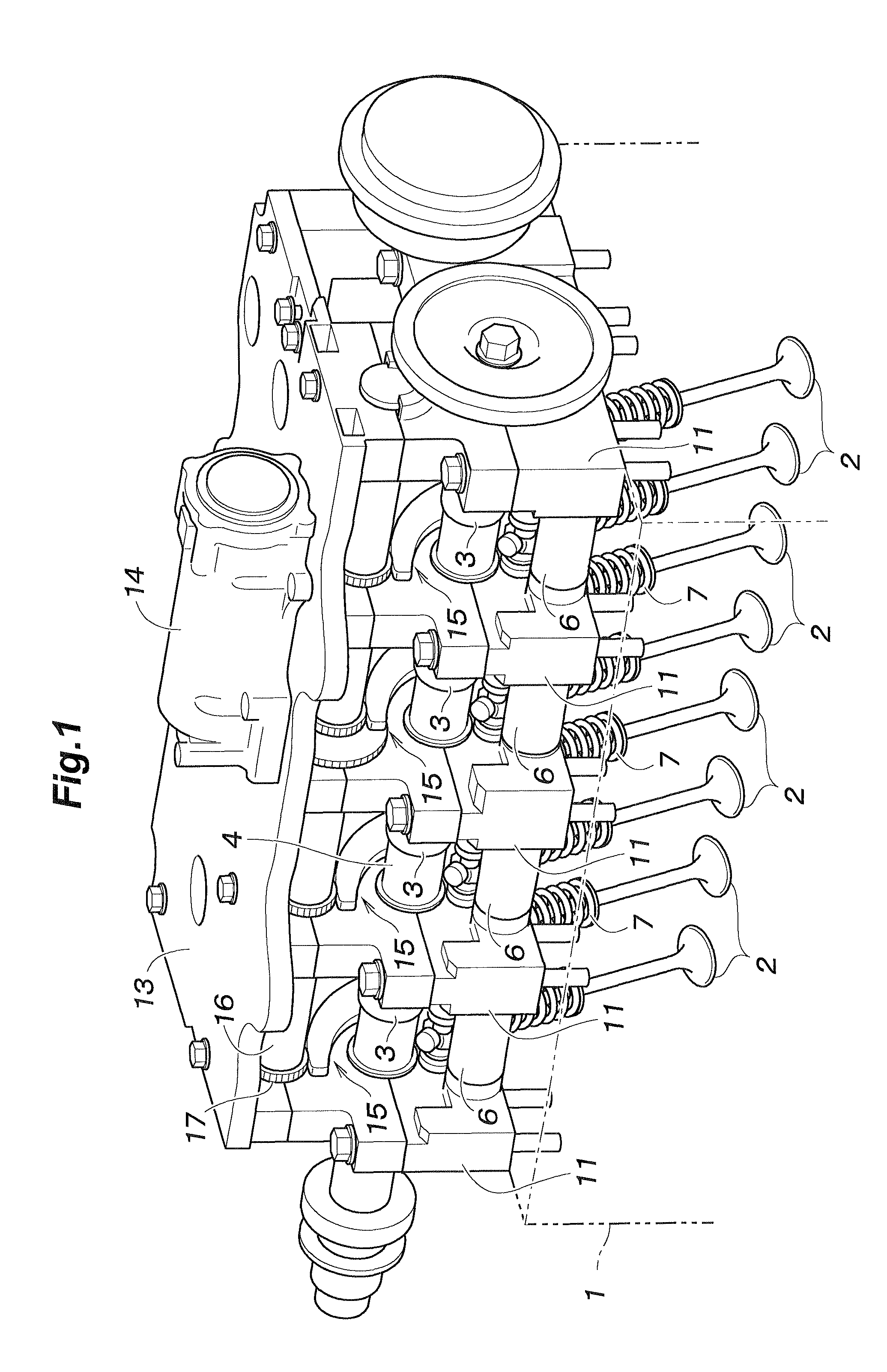
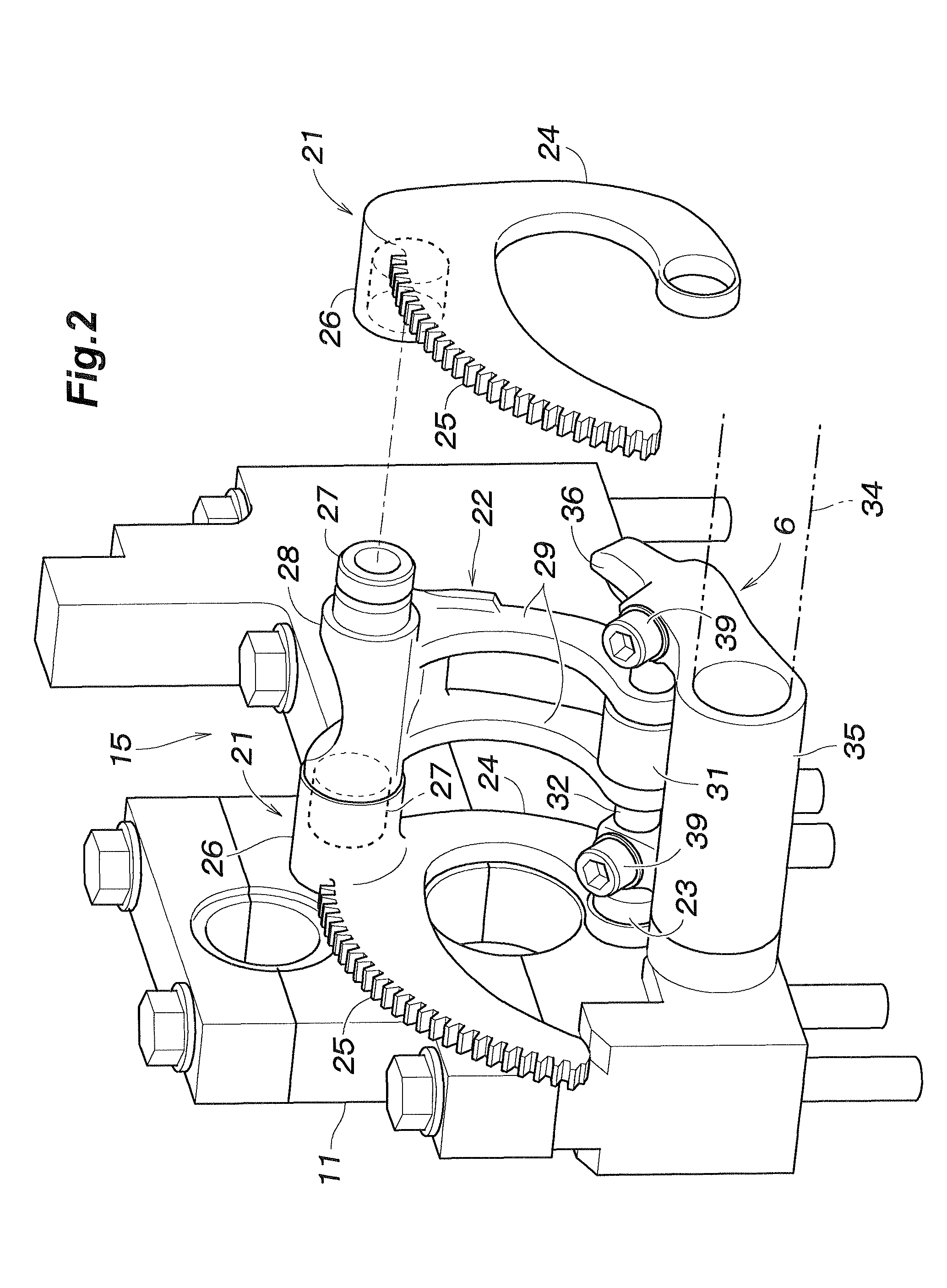
In a variable valve opening property internal combustion engine, a roller link (22) is provided with a cam roller (31) at a free end thereof which engages a cam (3) of a camshaft (4) and a pressure surface (47) of a spring device (41). The roller link is pivotally supported by a bearing portion of a control link (21) which can be adjusted in position by using an actuator (14). The roller link is additionally provided with a roller shaft (31) that engages a slipper surface of a rocker arm (6). The pressure surface of the spring device may be contoured or otherwise inclined so that the direction of action of the spring device on the cam roller can be directed in an optimum direction irrespective of the adjusted position of the pivot point of the roller link.

Description

CROSS REFERENCE TO COPENDING APPLICATION(S)[0001]Reference should be made to the following copending patent application(s) and the contents thereof as well as the contents of any related prior art mentioned therein are hereby incorporated in this application by reference.[0002]Ser. No. 12 / 203,563 filed Sep. 3, 2008.TECHNICAL FIELD[0003]The present invention relates to a variable valve opening property internal combustion engine that can change a valve opening property such as the lift of the exhaust and / or intake valves of the engine depending on the operating condition of the engine.BACKGROUND OF THE INVENTION[0004]Some of the recently developed gasoline and diesel internal combustion engines are fitted with a valve opening property varying mechanism to improve the output and fuel economy of the engine and reduce undesired emissions from the engine. A relatively known form of valve opening property varying mechanism is provided with low speed cams and high speed cams that can be in...

Claims


Application Information

Patent Timeline
Patent Type & Authority Patents(United States)
IPC IPC(8): F01L1/34
CPCF01L1/185F01L13/0015F01L13/0063F01L2001/0476F01L2001/467F01L2105/00F01L2305/00
Inventor TAKEMOTO, FUMIHISASUGIMOTO, MITSURUKOMURA, KIMINORIKOBAYASHI, TAKEOTOCHIKI, HIROKAZU
Owner HONDA MOTOR CO LTD
Why Eureka
Try Eureka