Transfer apparatus

a technology of transfer apparatus and transfer base, which is applied in the direction of mechanical control devices, process and machine control, instruments, etc., can solve the problems of increasing affecting the smooth movement of the lift base, and affecting the stability of vertical movement, so as to reduce the influence of biasing load and moment load and stable vertical movement

Active Publication Date: 2011-09-06
DAIHEN CORP
View PDF5 Cites 5 Cited by
  • Summary
  • Abstract
  • Description
  • Claims
  • Application Information

AI Technical Summary

Benefits of technology

The present invention has been proposed under the circumstances described above. It is therefore an object of the present invention to provide a transfer apparatus which is capable of reducing the influence of biasing load and moment load caused by a hand and a work to ensure stable vertical movement.

Problems solved by technology

When the positional deviation occurs, the vertical movement of the lift base may not be performed smoothly or the hand may not be held horizontally.
However, such an increase causes an increase in biasing load and moment load, which encourages the above-described disadvantage.

Method used


Image

  • Transfer apparatus
  • Transfer apparatus
  • Transfer apparatus

Examples


Embodiment Construction

Preferred embodiments of the present invention will be described below with reference to the accompanying drawings.

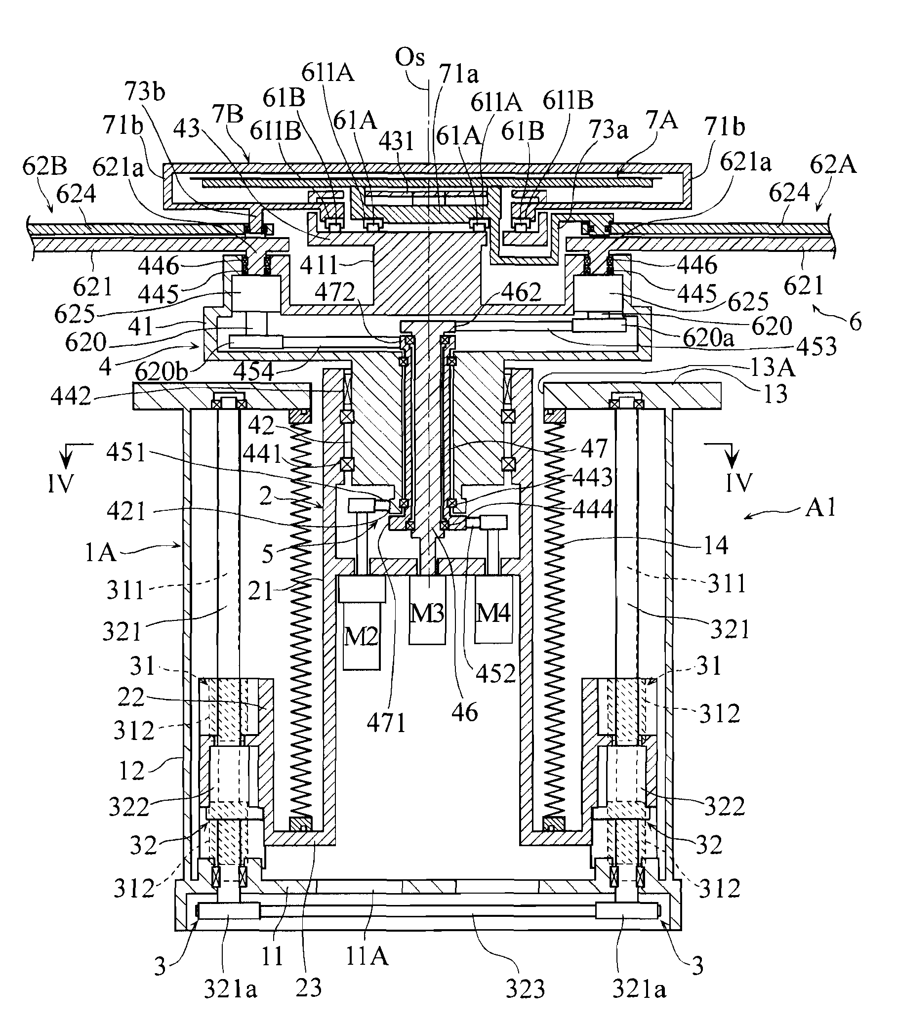
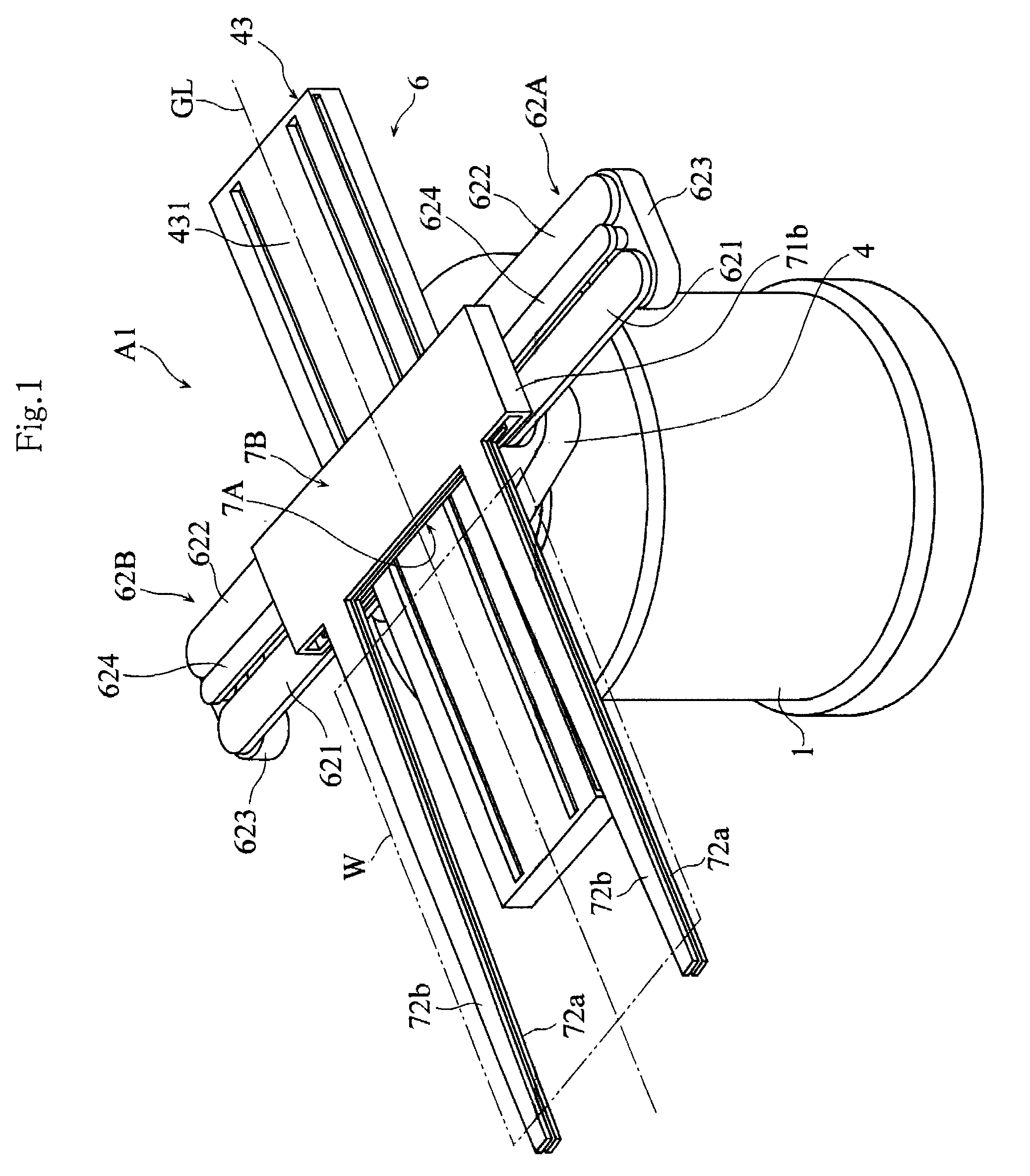
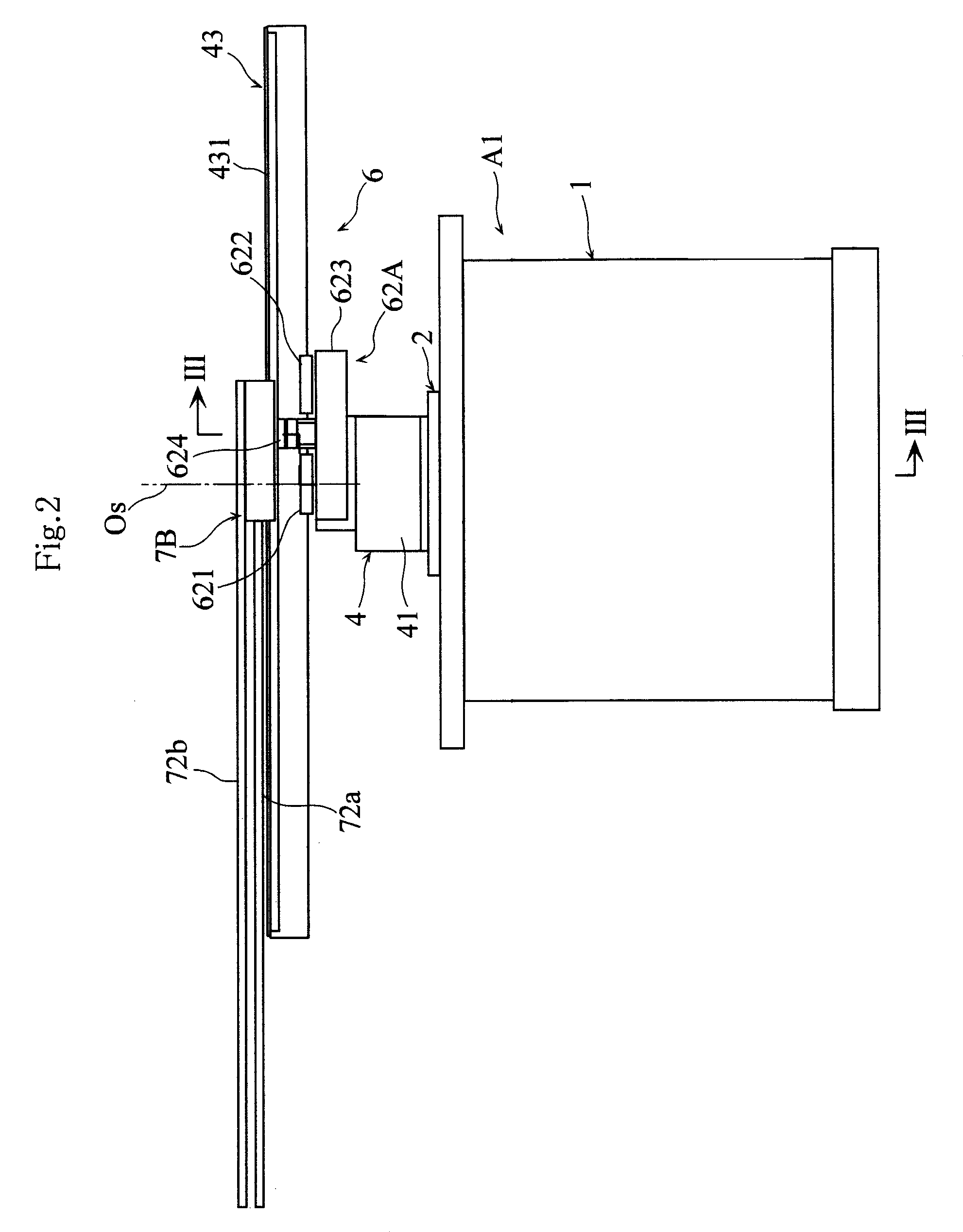
FIGS. 1-4 show a transfer apparatus according to the present invention. The transfer apparatus A1 may be used for transferring a work in the form of a thin plate such as a substrate for a liquid crystal display panel. As shown in FIGS. 1 and 3, the transfer apparatus A1 includes a stationary base 1, a lift base 2, a lifting mechanism 3 for vertically moving the lift base 2 relative to the stationary base 1, a rotary base 4 mounted on the lift base 2, and a rotating mechanism 5 for rotating the rotary base 4 about the vertical rotation axis Os. A linear moving mechanism 6 is mounted on the rotary base 4. A pair of hands 7A and 7B are individually mounted on the linear moving mechanism 6. The hands 7A and 7B serve to hold the work W in a horizontal posture.

As better shown in FIG. 3, the stationary base 1 includes a housing 1A having a generally columnar outer configuratio...


PUM


Abstract

A transfer apparatus includes a stationary base, a lift base, a lifting mechanism for vertically moving the lift base, a rotary base mounted to the lift base, a rotating mechanism for rotating the rotary base about a vertical rotation axis, a linear moving mechanism supported by the rotary base, and a work hand supported by the linear moving mechanism. The lifting mechanism includes a slide guide mechanism for vertical movement of the lift base, and first and second screw-feeding mechanisms. Each screw-feeding mechanism includes a rotatable vertical screw shaft, and a nut member provided on the lift base and screwed onto the screw shaft. The first and the second screw-feeding mechanisms are spaced from each other, with the rotation axis of the rotary base being located between the first and the second screw-feeding mechanisms.

Description

BACKGROUND OF THE INVENTION1. Field of the InventionThe present invention generally relates to a transfer apparatus. In particular, it relates to a transfer apparatus for linearly transferring a thin work such as a wafer and a glass substrate used in the fabrication process of semiconductor devices or liquid crystal display panels.2. Description of the Related ArtA transfer apparatus provided with a linear moving mechanism for moving a work-holding hand along a linear path has a simpler structure and is less expensive than a jointed-arm robot. Thus, such a linear transfer apparatus is often used for carrying in or out a thin work (a wafer, a glass substrate, etc.) relative to a process chamber in manufacturing semiconductor devices or liquid crystal display panels, for example.An example of a conventional linear transfer apparatus is disclosed in JP-A-2005-125479. The transfer apparatus disclosed includes a link arm mechanism supported by a rotary base. A hand for horizontally holdi...

Claims


Application Information

Patent Timeline
Patent Type & Authority Patents(United States)
IPC IPC(8): B25J18/04
CPCB25J18/04H01L21/67742Y10T74/20305
Inventor URATANI, TAKAFUMISADO, DAISUKEMATSUO, HIDEKI
Owner DAIHEN CORP
Why Eureka
Try Eureka