Electrical power receptacle with rotatable USB jacks

a technology of electric power receptacles and usb ports, which is applied in the direction of flexible/turnable line connectors, electric discharge lamps, coupling device connections, etc., can solve the problems of increasing the burden, increasing the limitations of use, and not being able to connect directly with the public electrical power distribution system, so as to reduce the overall manufacturing cost, simplify the structure design, and direct electrical connection interface

Active Publication Date: 2011-09-06
POWERTECH INDAL
View PDF5 Cites 44 Cited by
  • Summary
  • Abstract
  • Description
  • Claims
  • Application Information

AI Technical Summary

Benefits of technology

[0007]As per the aforementioned issues, a primary objective of the present invention is to provide an electrical power receptacle with rotatable USB Jacks in accordance with the structural design thereof for solving the restrictions in USB connection directions with regards to the conventional fixed type USB jacks. Furthermore, the design of USB jack assembly according to the present invention provides a simplified and direct electrical connection interface for a variety of electronic devices adapted for the USB interface connection. Moreover, the electrical power receptacle with rotatable USB jacks according to the present invention simplifies the structure design, thereby decreasing the overall manufacturing cost.
[0009]As per the aforementioned electrical power receptacle with rotatable USB jacks according to the present invention, the USB jack assembly with a simplified design and low manufacturing cost may electrically connect to USB connectors of the electronic devices directly, instead of indirectly connecting to an intermediate electronic apparatus first, thereby increasing the power efficiency and convenience of use. Moreover, the rotating member of the electrical power receptacle with rotatable USB jacks is capable of adjusting the direction of the USB jack assembly with respect to various application environments and situations. In other words, the rotating member can change the rotational directions so as to reduce the restrictions in application range and prevent from damaging the USB connector, so that the service life of the USB connector will not be shortened due to improper operations in practice.

Problems solved by technology

Because the main design factors for portable electronic devices emphasize on how to reduce an overall dimensional size or overall weight, it is not suitable to connect with the public electrical power distribution system for electrical power directly.
Thus, the limitations of the USB interface connection, no only increase the burden for manufactures to redesign circuitry for the main electronic apparatuses with regards to the USB connection, but also increase the limitations in use.
Because the old design for electronic apparatuses does not have USB jacks, these old apparatuses are not compatible with the present peripheral electronic devices by applying USB connectors.
Thus, as long as the USB connectors of the portable electronic devices connect to the aforementioned fixed USB jacks, the movement range of the portable electronic devices is restricted by the USB connection direction, the convenience of mobility is also reduced, and the USB connectors applied for portable electronic devices are vulnerable to be damaged due to improper operations, thereby reducing the service life thereof.

Method used


Image

  • Electrical power receptacle with rotatable USB jacks
  • Electrical power receptacle with rotatable USB jacks
  • Electrical power receptacle with rotatable USB jacks

Examples


first embodiment

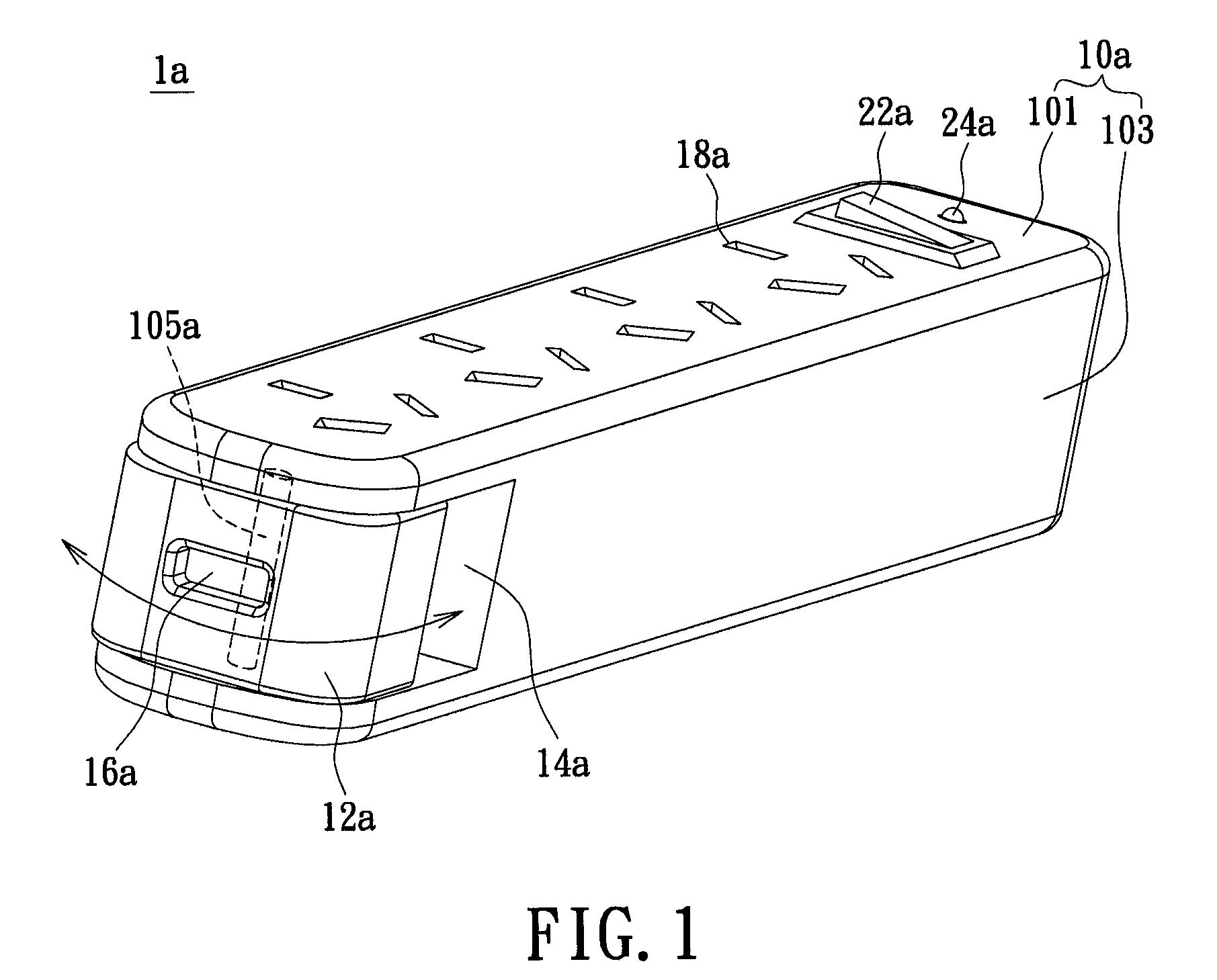
[0018]First please refer to FIG. 1, in which an exploded diagram of the electrical power receptacle with rotatable USB jacks in accordance with certain aspects of the present technique is demonstrated. An electrical power receptacle with rotatable USB jacks 1a comprises a main body 10a, at least an electrical outlet assembly 18a, a rotating member 12a, and at least a USB jack assembly 16a. Herein, the main body 10a further includes a first housing member 101, a second housing member 103, and a shaft section 105a. The electrical power receptacle with rotatable USB jacks 1a further includes an accommodating section 14a, a power switch 22a, and an indicator 24a.

[0019]The main body 10a is constructed by the first housing member 101 and the second housing member 103. The electrical outlet assemblies 18a are disposed on the main body, which allow the electronic devices to connect to the electrical outlet assemblies 18a for receiving the public electrical power. In the embodiment, the sha...

second embodiment

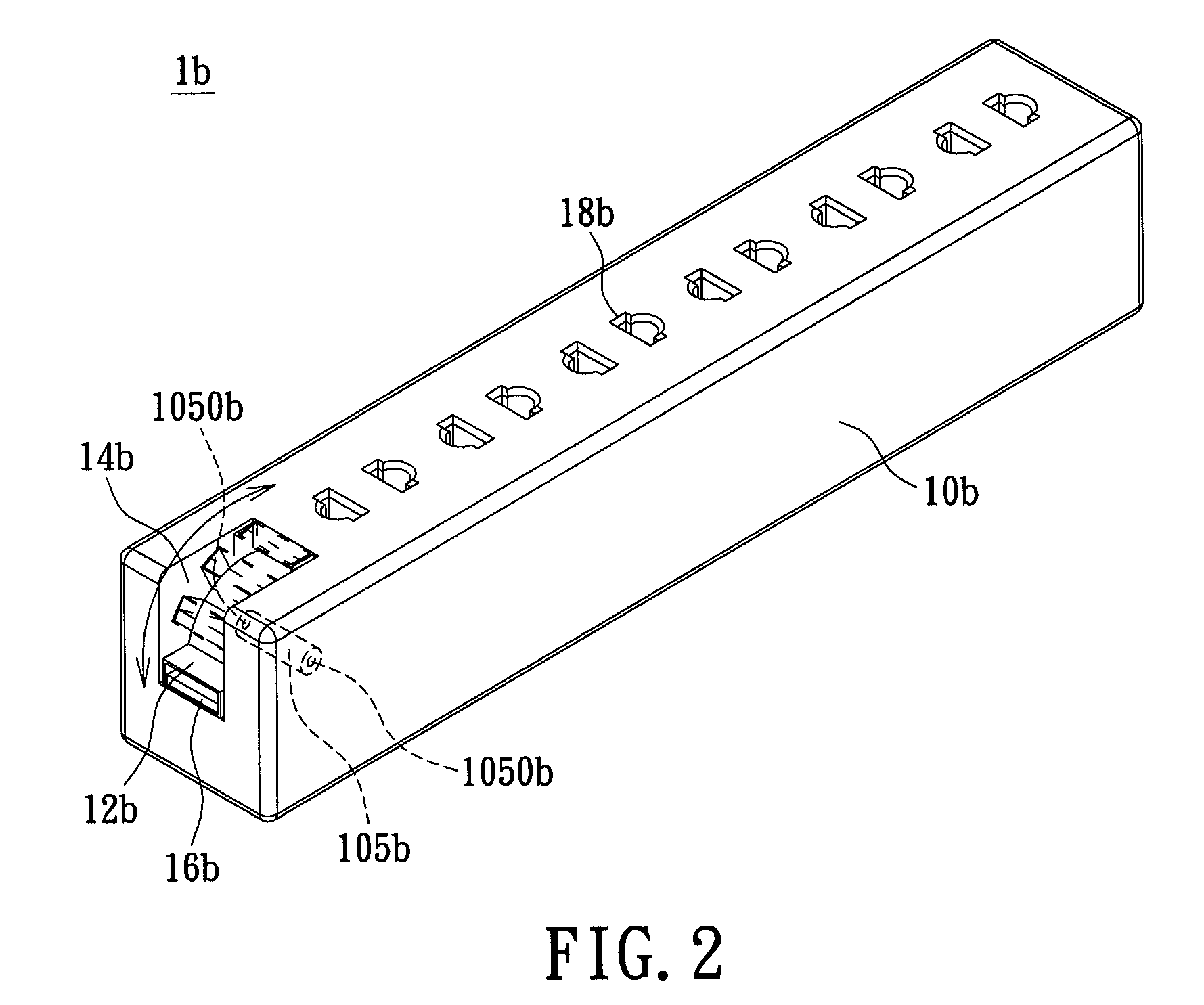
[0021]Next please refer to FIG. 2 in conjunction with FIG. 1, in which an exploded diagram of the electrical power receptacle with rotatable USB jacks according to the present invention is demonstrated. An electrical power receptacle with rotatable USB jacks 1b has identical elements and similar connecting relationship with respect to that of FIG. 1, yet the only structural difference is a design of a shaft section 105b, a rotating member 12b, and an accommodating section 14b configured with a main body 10b. The shaft section 105b is disposed on the peripheral regions of the main body 10b. The accommodating section 14b has changed it's shape and size with respect to the size and shape of the rotating member 12b. according to the structural design of the rotating member 12b and the accommodating section 14b configured on the main body 10b, the rotating member 12b is capable of rotating along a predetermined axis of the shaft section 105b around 90 degrees inside the accommodating sec...

third embodiment

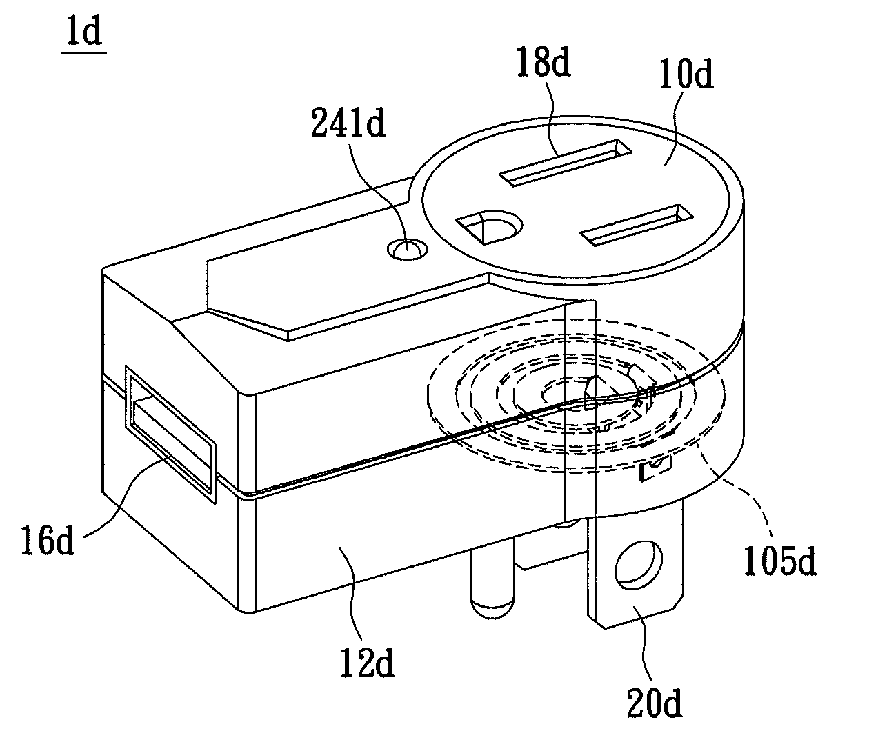
[0022]Next please refer to FIG. 3, in which an exploded diagram of the electrical power receptacle with rotatable USB jacks according to the present invention is demonstrated. An electrical power receptacle with rotatable USB jacks 1c has identical elements and similar connecting relationship with respect to that of FIG. 1, yet the only structural difference is a design of a shaft section 105c and a rotating member 12c configured with a main body 10c. The shaft section 105c is disposed on the front portion of the main body 10c, but is not limited thereto, for example, the shaft section 105c may disposed on the rear portion or middle portion of the main body 10c. As shown in FIG. 3, the shaft section 105c is conversely disposed on the main body 10c. The rotating member 12c coupled to the shaft section 105c is rotatable with respect to a predetermined axis of the shaft section 105c transversely outside of the main body. As such, the rotating member 12c of the embodiment may have a rot...


PUM


Abstract

Disclosed is an electrical power receptacle with rotatable USB jacks comprising a main body including at least one shaft section; at least one electrical outlet assembly being disposed on the main body; a rotating member, coupled to the main body via the shaft section, being rotatable along the shaft section, and a rotational angle thereof being determined with respect to structural designs; and at least one USB jack assembly, being disposed on the rotating member and rotatable along with the rotational movement of the rotating member. An electric plug assembly with conducting prongs is disposed on the main body for connecting with the public electrical power distribution system. Thus, by adjusting the direction of rotation in accordance with the USB jack assemblies according to the present invention, the restriction in application range thereof decreases.

Description

BACKGROUND OF THE INVENTION[0001]1. Field of the Invention[0002]The present invention relates to an electrical power receptacle, in particular, to an electrical power receptacle with rotatable USB jacks.[0003]2. Description of Related Art[0004]With the present continuous development of modern society, more and more electronic devices are utilized in public. To operate the electronic devices, electrical power supplies are required to drive the electronic devices. Generally specking, peripheral electronic devices are usually designed as portable electronic devices. Because the main design factors for portable electronic devices emphasize on how to reduce an overall dimensional size or overall weight, it is not suitable to connect with the public electrical power distribution system for electrical power directly. Consequently, a conventional method for supplying electrical power to the conventional peripheral electronic devices is to utilize USB connectors which are capable of connecti...

Claims


Application Information

Patent Timeline
Patent Type & Authority Patents(United States)
IPC IPC(8): H01R39/00
CPCH01R35/04H01R13/6675H01R25/003H01R25/00
Inventor LEE, YU-LUNGHSU, JUNG-HUIKUO, MING-CHOU
Owner POWERTECH INDAL
Why Eureka
Try Eureka