
Keyboard apparatus

a keyboard and keypad technology, applied in the field of keyboard apparatus, can solve the problems of different voltage signals, hysteresis characteristics, and inability to specify the position of the plunger b>41/b> from the voltage signal, so as to enhance the precision of detecting the position, suppress the distance between each of the reflection plates and the optical sensors, and enhance the effect of hysteresis generated in the electric signal according to the quantity

Inactive Publication Date: 2011-09-06
YAMAHA CORP
View PDF10 Cites 8 Cited by
  • Summary
  • Abstract
  • Description
  • Claims
  • Application Information

AI Technical Summary

Benefits of technology

[0010]In view of the foregoing circumstance, the present invention aims to provide a keyboard apparatus that can enhance the precision in detecting the position of the movable member.
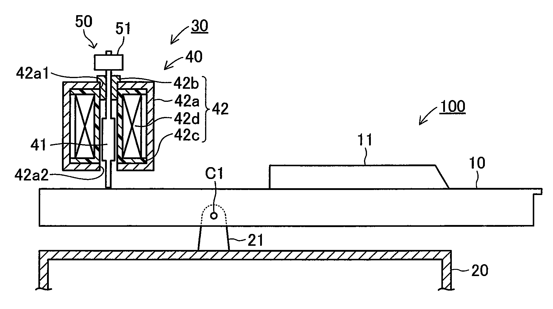
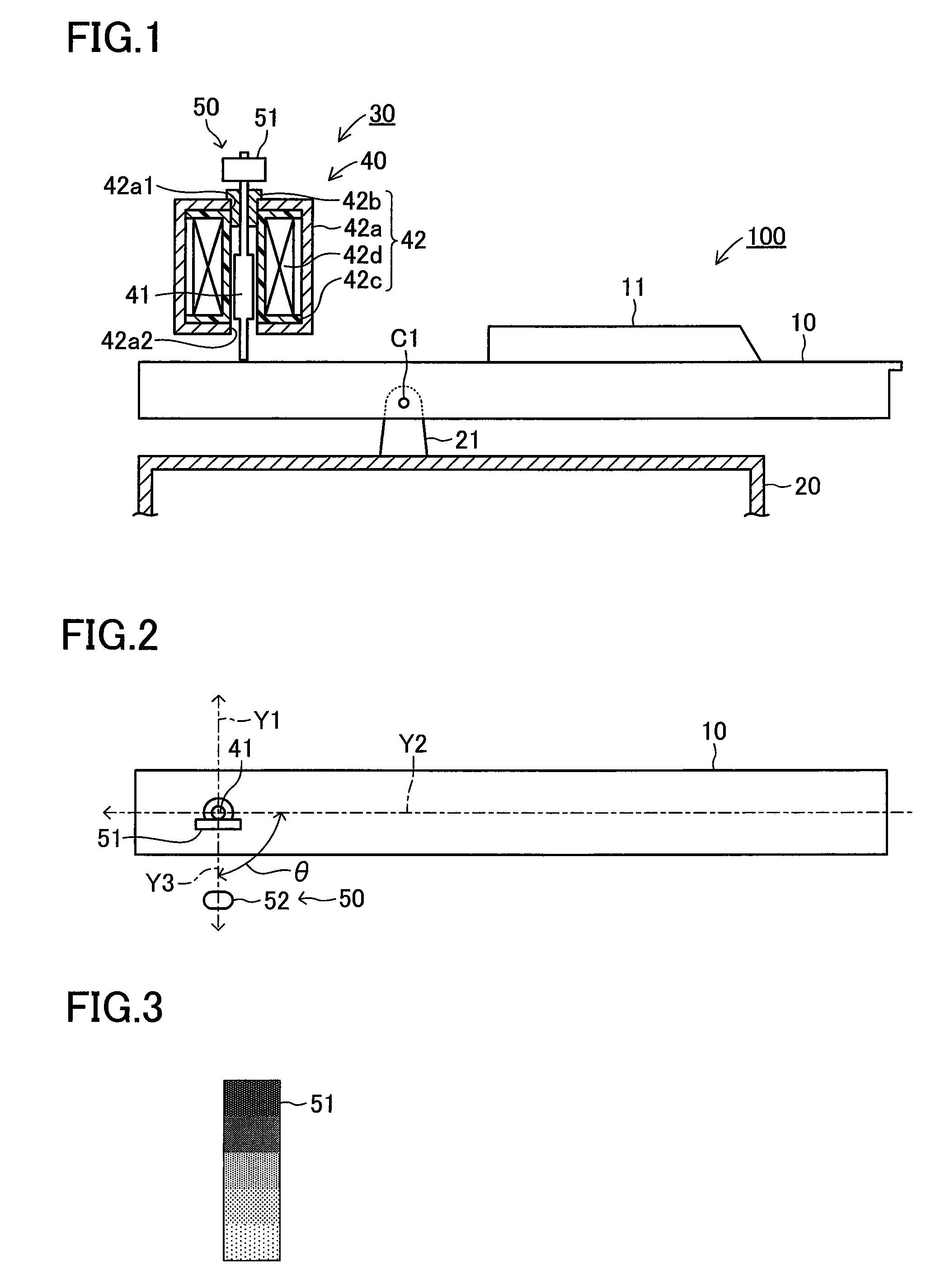
[0015]In the present invention thus configured, the reflection surfaces of the reflection plates are directed in the lateral direction of the keys, and the optical sensors are arranged at the position apart from the longitudinal axes of the keys in the lateral direction. Therefore, even if the movable members clatter in the longitudinal direction in accordance with the operation of depressing and releasing the keys, the variation in the distance between each of the reflection plates and the each of the optical sensors can be suppressed to be small, whereby the hysteresis generated in the electric signal according to the quantity of received light outputted from each of the optical sensors can be suppressed. Accordingly, the keyboard apparatus that can enhance the precision in detecting the position of each of the movable members can be provided with reduced cost.

Problems solved by technology

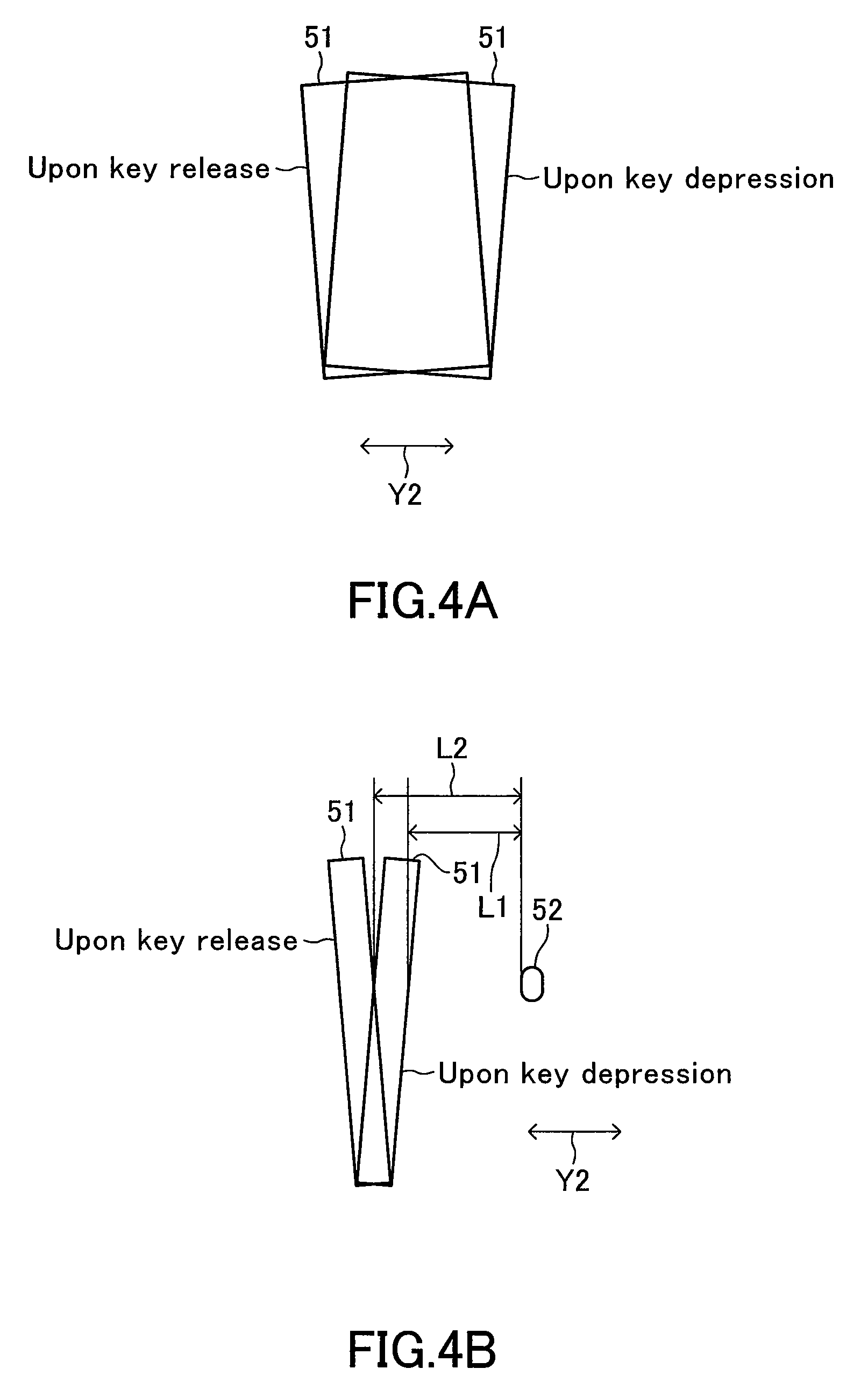
Therefore, as shown in FIG. 5A, a problem arises that the voltage signal outputted from the optical sensor 52 is different between the case of the key depression and the case of the key release, i.e., a hysteresis characteristic is generated.
Due to this hysteresis, the voltage signal outputted from the optical sensor 52 is different between the case of the key depression and the case of the key release, even if the plunger 41 is located at the position of the same height, thereby entailing a problem that the position of the plunger 41 cannot be specified from the voltage signal.
A method of correcting the hysteresis has been considered, but a complicated process is needed for this method.

Method used


Image

  • Keyboard apparatus
  • Keyboard apparatus
  • Keyboard apparatus

Examples


Embodiment Construction

[0025]An embodiment of the present invention will be described below with reference to the drawings. FIG. 1 is a schematic sectional view showing an embodiment of a keyboard apparatus 100 according to the present invention. FIG. 2 is a top view showing the keyboard apparatus 100 in which only a plunger 41 of an electromagnetic solenoid in FIG. 1 is left. FIG. 3 is a front view of a reflection plate 51 shown in FIG. 1. In the description below, the “vertical direction, lateral direction, and longitudinal direction” of the keyboard apparatus 100 mean the “vertical direction, lateral direction, and longitudinal direction” as viewed from a player who plays the keyboard apparatus 100.

[0026]The keyboard apparatus 100 is used for an electronic keyboard instrument, for example. As shown in the figures, the keyboard apparatus 100 includes plural white keys 10 and black keys 11, which serve as performance operation elements, a frame 20, and a driving unit 30. The white keys 10 and the black k...


PUM


Abstract

A keyboard apparatus includes plural keys, electronic actuators, reflection plates, and optical sensors. Each key extends in the longitudinal direction and pivots in the vertical direction about a support in accordance with key depression and release. Each electronic actuator has a movable member that displaces vertically when interlocking with a key's pivot movement so as to apply a reaction force against key depression. Each plural reflection plate is fixed to the electronic actuator's movable member, wherein the reflection surface faces the lateral direction of each of the keys. The light reflectance changes along the displacing direction of the movable member. Each optical sensor is arranged apart from the longitudinal axis of the keys in the lateral direction. It emits light toward the reflection plate and receives the reflected light from the reflection plate so as to output an electric signal according to the quantity of received light.

Description

BACKGROUND OF THE INVENTION[0001]1. Field of the Invention[0002]The present invention relates to a keyboard apparatus having plural keys, and more particularly to a keyboard apparatus having electronic actuators that apply a reaction force with respect to the operation of depressing the plural keys.[0003]2. Description of the Related Art[0004]A natural keyboard instrument such as an acoustic piano or the like is configured to generate a live sound by a hammer, which rotates with the key depression, striking a string, for example. The natural keyboard apparatus of this type has a so-called action mechanism provided between a key, which is a performance operation element, and a hammer. A player receives a unique reaction force (key damping force) from the key by this action mechanism. Specifically, a feeling of a key touch specific to the natural keyboard instrument can be obtained by providing the action mechanism.[0005]On the other hand, in a conventional electronic keyboard instrum...

Claims


Application Information

Patent Timeline
Patent Type & Authority Patents(United States)
IPC IPC(8): G10H3/06
CPCG10H1/346G10H2220/305G10H2220/311
Inventor KOMATSU, AKIHIKO
Owner YAMAHA CORP
Learn More