
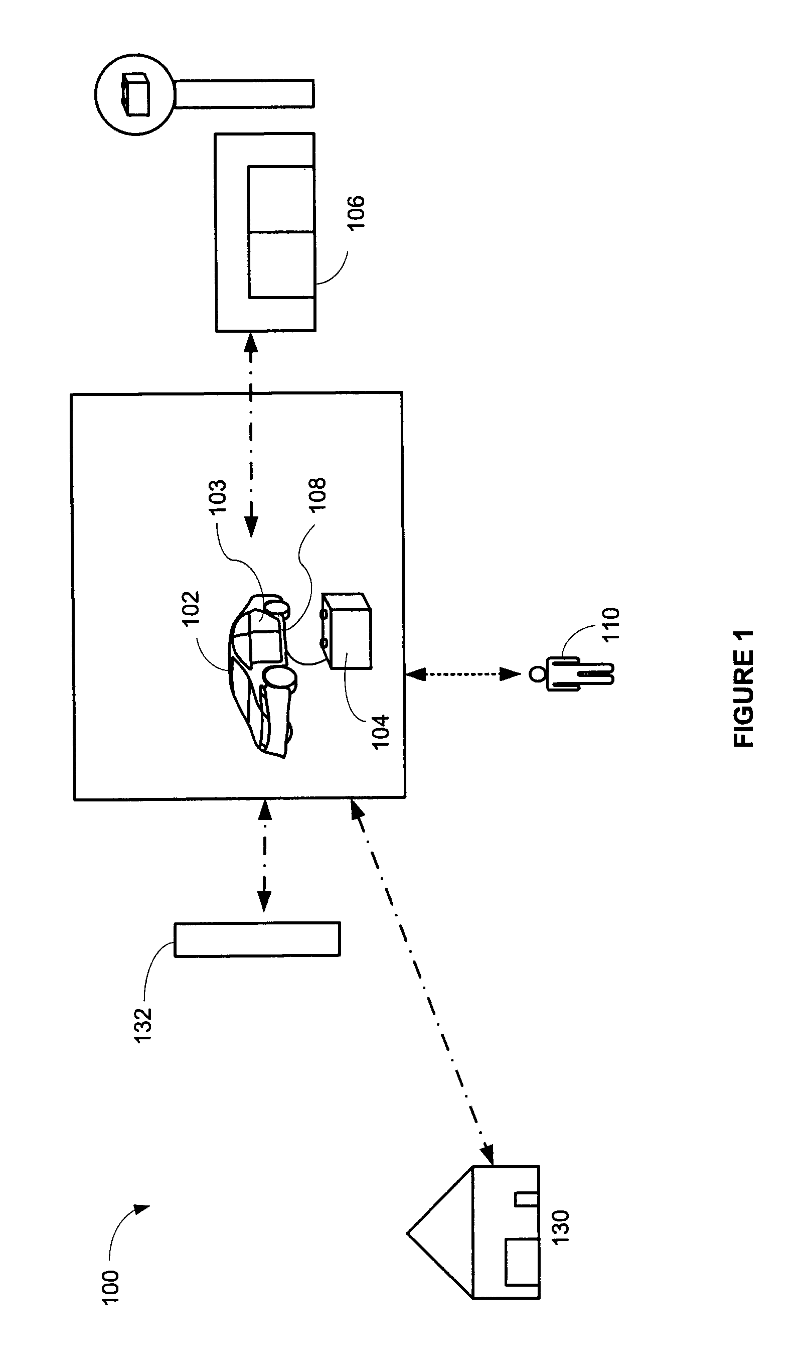
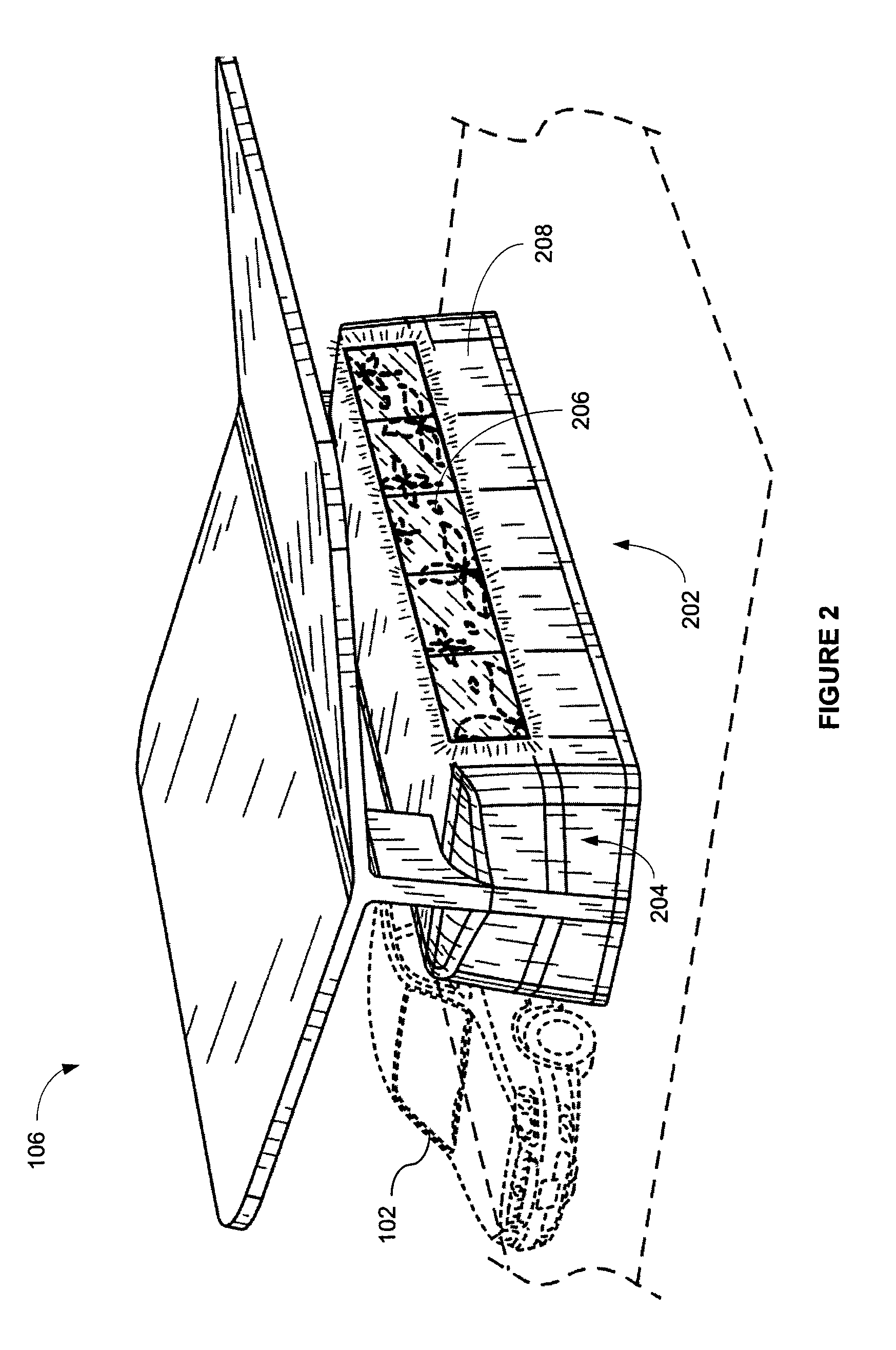
Battery exchange station

a battery exchange station and battery technology, applied in the field of electric cars, can solve the problems of many of these clean engine technologies that are not yet practical, hybrid vehicles do not eliminate the need for fossil fuels, and the dependence on limited foreign sources, so as to reduce the dependence on fossil fuels and prolong the battery recharge time

Active Publication Date: 2011-09-06
CHARGE PEAK
View PDF37 Cites 113 Cited by
  • Summary
  • Abstract
  • Description
  • Claims
  • Application Information

AI Technical Summary

Benefits of technology

This solution reduces the electric vehicle's dependence on fossil fuels, lowers the overall cost of ownership, and enables continuous vehicle availability by leveraging renewable energy sources for charging, addressing the limitations of existing battery technologies.

Problems solved by technology

Unfortunately, fossil fuels, like oil, used to power automobiles have numerous drawbacks including: a dependence on limited foreign sources for these fossil fuels, pollution, and climate change.
However, hybrid vehicles do not eliminate the need for fossil fuels.
However, many of these clean engine technologies are not yet practical.
For example, fuel cell vehicle are still in the development stage and are expensive.
Similarly, battery technology has not advanced to the point where batteries can power electric vehicles for long distances.
Batteries are costly and may add as much as 40% to the cost of a vehicle.
Furthermore, batteries can take many hours to recharge.
Thus, the long battery recharge time may no longer be relevant to a user of an electric vehicle who is traveling beyond the range of the battery.

Method used


Image

  • Battery exchange station
  • Battery exchange station
  • Battery exchange station

Examples


Embodiment Construction

[0059]Reference will now be made in detail to embodiments, examples of which are illustrated in the accompanying drawings. In the following detailed description, numerous specific details are set forth in order to provide a thorough understanding of the present invention. However, it will be apparent to one of ordinary skill in the art that the present invention may be practiced without these specific details. In other instances, well-known methods, procedures, and components have not been described in detail so as not to unnecessarily obscure aspects of the embodiments.

[0060]The terminology used in the description of the invention herein is for the purpose of describing particular embodiments only and is not intended to be limiting of the invention. As used in the description of the invention and the appended claims, the singular forms “a,”“an,” and “the” are intended to include the plural forms as well, unless the context clearly indicates otherwise. It will also be understood tha...


PUM

PropertyMeasurementUnit
of timeaaaaaaaaaa
of timeaaaaaaaaaa
degrees of freedomaaaaaaaaaa

Abstract

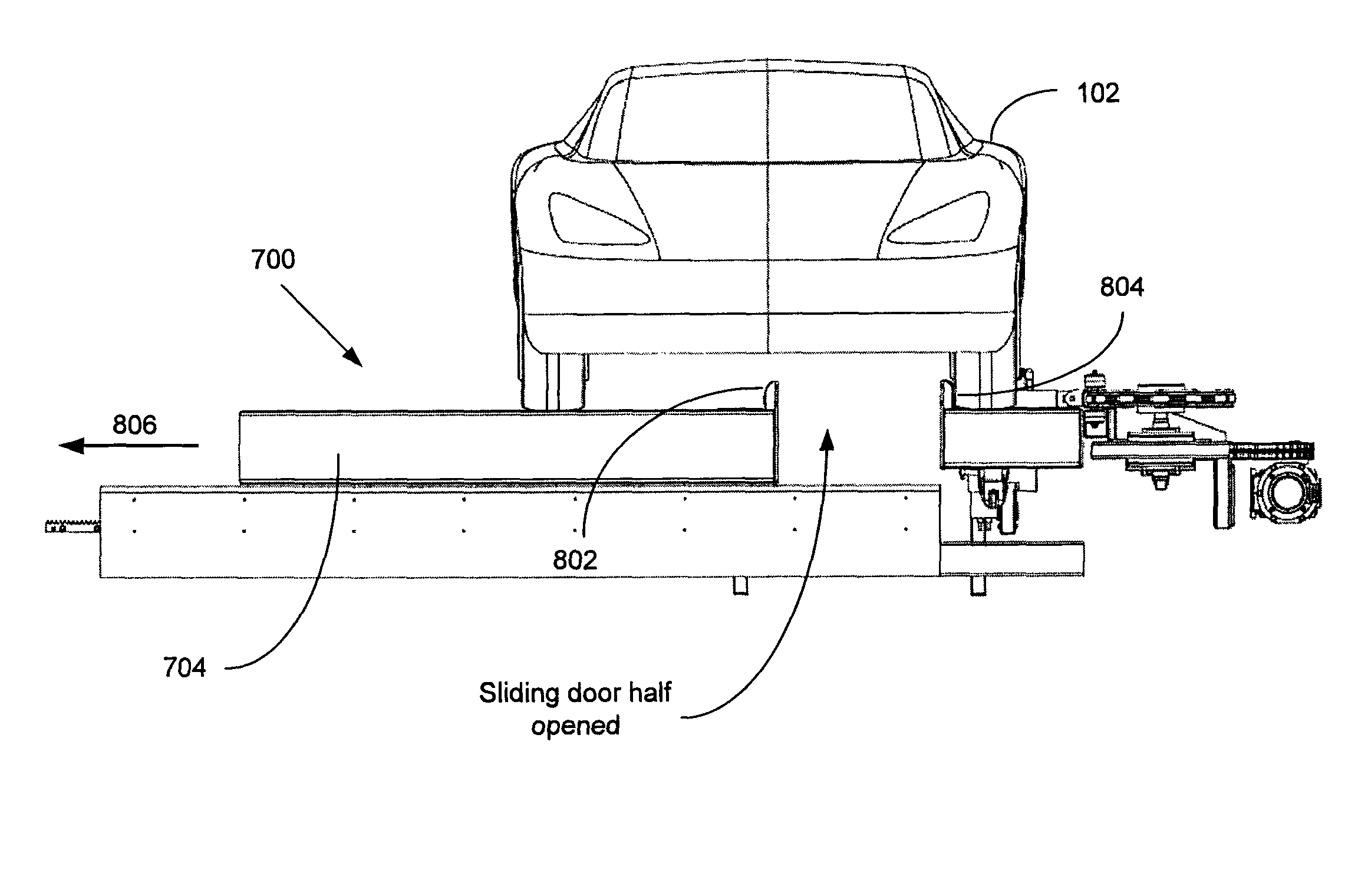
At the battery exchange station a discharged battery is removed and a charged battery is inserted into an electric vehicle. The battery is inserted and removed along a vertical axis, i.e., into and out of the bottom of the vehicle. The battery exchange system is located in a service bay under the vehicle. A sliding door system creates an opening above the service bay. A vehicle is received over the sliding door system, such that at least one wheel of the vehicle rests on the conveyor system. The door slides in a first direction while allowing the conveyor system to slide in a direction opposite the first direction. The conveyor system also supports the at least one wheel of the vehicle while the door and conveyor slide in opposite directions. The sliding of the door and the sliding of the conveyor system occur at least partially simultaneously.

Description

RELATED APPLICATIONS[0001]This Application is a divisional of application Ser. No. 12 / 563,103, filed Sep. 18, 2009, which is a United States National Stage Application filed under 35 U.S.C. §371 of PCT Patent Application Serial No. PCT / US2009 / 057596 filed Sep. 18, 2009, which claims the benefit of U.S. Provisional Patent Application No. 61 / 166,239, filed Apr. 2, 2009; U.S. Provisional Patent Application No. 61 / 206,913, filed Feb. 4, 2009; U.S. Patent Application No. 61 / 149,690, filed Feb. 3, 2009; and U.S. Provisional Patent Application No. 61 / 098,724, filed Sep. 19, 2008, all of which are incorporated by reference herein in their entirety.FIELD OF THE INVENTION[0002]The present invention relates generally to the field of electric cars with exchangeable batteries and more specifically relates to the exchange stations for swapping such electric batteries.BACKGROUND OF THE INVENTION[0003]The vehicle (e.g., cars, trucks, planes, boats, etc.) is an integral part of the modern economy. U...

Claims


Application Information

Patent Timeline
Patent Type & Authority Patents(United States)
IPC IPC(8): H02J7/00B60P1/04B65G67/00H01M50/202H01M50/204H01M50/242H01M50/244H01M50/249
CPCB60K1/04B60L11/1822B60L11/185B60L11/1877B60L11/1879B60S5/06H01M2/1083Y10T29/49815B60L2200/26Y02E60/12Y02T10/7005Y02T10/7011Y02T10/7016Y02T10/705Y02T10/7072Y02T90/124Y02T90/128Y02T90/14Y02T90/16B60K2001/0438Y02T10/92Y02T90/121B60K2001/0472B60L50/51B60L53/80B60L53/11B60L50/66B60L50/64H01M50/204H01M50/249H01M50/202H01M50/242H01M50/244Y02T10/70Y02T90/12
Inventor AGASSI, SHAIHEICHAL, YOAV
Owner CHARGE PEAK
Learn More