Linear actuator

Active Publication Date: 2011-09-13
LINAK AS
View PDF21 Cites 22 Cited by
  • Summary
  • Abstract
  • Description
  • Claims
  • Application Information

AI Technical Summary

Benefits of technology

[0006]The actuator according to the invention is characterized in that the overload clutch is arranged in connection with the first stage or one of the first stages in the reduction gear, which means that the overload clutch is not subjected to so great moment loads, whereby it may be made more compact and reliable. The lower moment load also allows the speed of the actuator to be increased relative to the known structure by selecting spindles with greater pitche

Problems solved by technology

This position of the overload clutch also puts a limit on the spe

Method used


Image

  • Linear actuator
  • Linear actuator
  • Linear actuator

Examples


Example

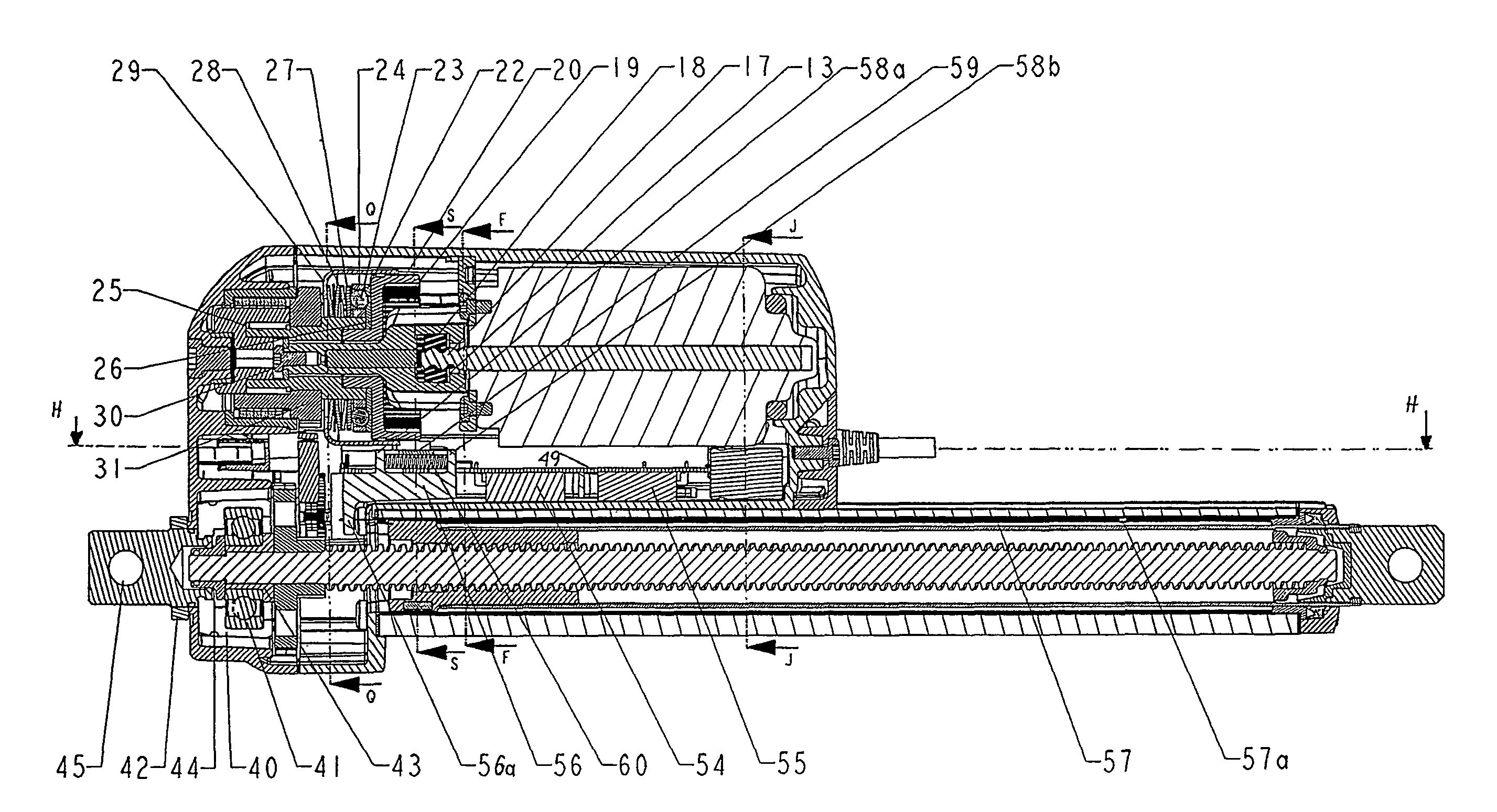
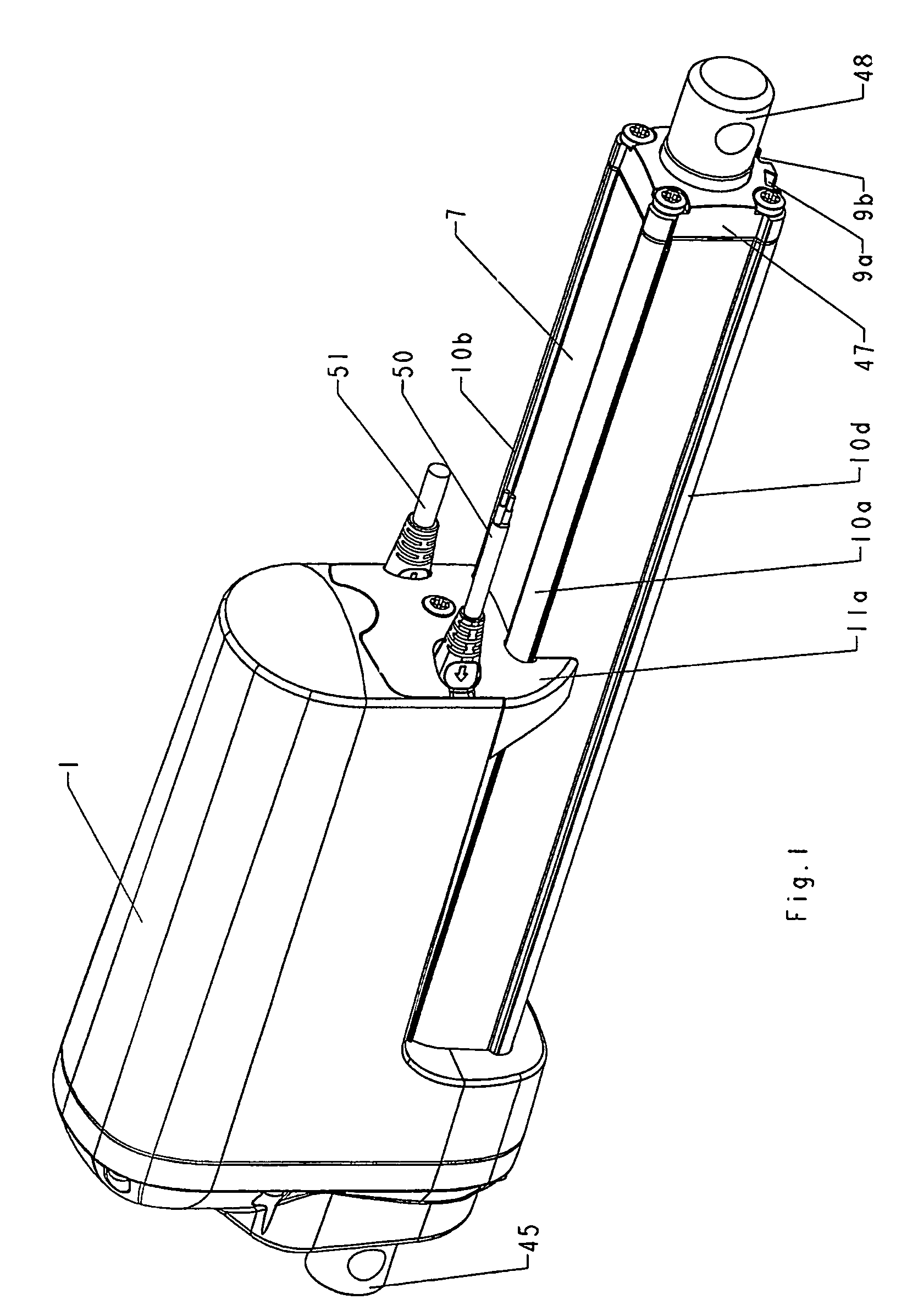
[0038]As will appear from the drawing (FIG. 4), the main components of the actuator are formed by a cabinet 1, a reversible electric motor 2, a reduction gear 3 with several stages, a spindle 4, a spindle nut 5, an activation element 6 in the form of a tubular piston, also called the inner pipe, a guide 7 therefor, also called the outer pipe, and finally a rear mount 8.

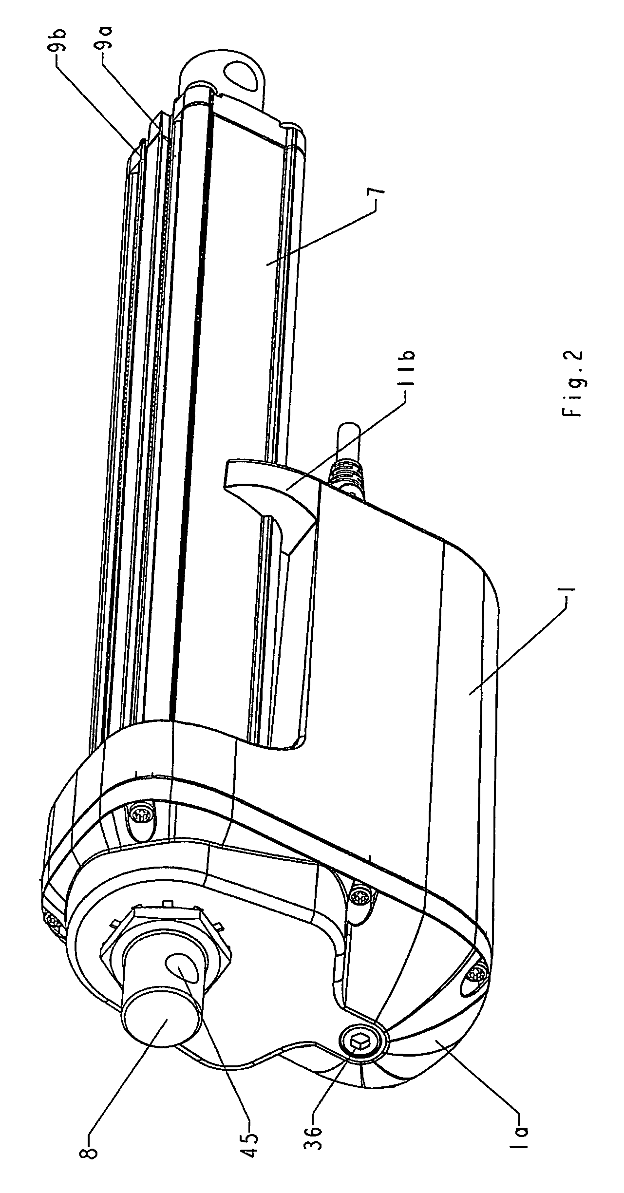
[0039]The cabinet 1, which is made of moulded aluminium for strength purposes, has an end cover 1a which is mounted with screws, and the joint is moreover water-tight (FIGS. 1 and 2). The outer pipe 7, which is an extruded aluminium pipe having an essentially square cross-section, is mounted with screws, and here, too, the joint is water-tight. On its one side, the outer pipe 7 is provided with two longitudinal grooves 9a, 9b, which may be used for the mounting of extra equipment. Further, the pipe 7 is extruded with a screw channel in each corner, which externally forms a longitudinal, projecting strip 10a-d having a...


PUM


Abstract

A linear actuator includes a reversible electric motor which drives a spindle via a reduction gear with several stages and an activation element connected with it, and an overload clutch in connection with the first stage or one of the first stages in the reduction gear. This is advantageous in terms of structure and load and greater flexibility is achieved in the construction of the structure.

Description

BACKGROUND OF THE INVENTION[0001]1. Field of the Invention[0002]The present invention relates to a linear actuator.[0003]2. The Prior Art[0004]An actuator for industrial purposes of the above-mentioned type is marketed by the U.S. company Warner Electric Brake & Clutch Company under the trade mark ELECTRAC. The actuator is provided with an overload clutch in the form of a ball and ratchet clutch arranged between the spindle and the output side of the reduction gear. This position of the overload clutch also puts a limit on the speed of the actuator because of the high moment load on the clutch. The actuator has been marketed in an unchanged version at least for the last 30 years.[0005]The object of the invention is to provide an actuator of this type with improved properties and greater flexibility in the building of the structure.SUMMARY OF THE INVENTION[0006]The actuator according to the invention is characterized in that the overload clutch is arranged in connection with the firs...

Claims


Application Information

Patent Timeline
IPC IPC(8): F16H25/22F16H25/20
CPCF16H25/2021F16H2025/2081Y10T74/18576Y10T74/18688Y10T74/18696F16H2025/2087
Inventor CHRISTENSEN, BRUNOJACOBSEN, FINNKRISTIANSEN, KJELD
Owner LINAK AS
Why Eureka
Try Eureka