Vibration-type cleaning device for contact lenses

a cleaning device and vibration-type technology, applied in the direction of electrostatic cleaning, rigid containers, apparel, etc., can solve the problems of cornea damage, time-consuming cleaning process, and ineffective cleaning methods mentioned above, so as to save the cost of buying different cleaning devices

a cleaning device and vibration-type technology, applied in the direction of electrostatic cleaning, rigid containers, apparel, etc., can solve the problems of cornea damage, time-consuming cleaning process, and ineffective cleaning methods mentioned above, so as to save the cost of buying different cleaning devices

US8015987B2Inactive Publication Date: 2011-09-13ZAKUTIN DAVID MICHAEL

Image

  • Vibration-type cleaning device for contact lenses
  • Vibration-type cleaning device for contact lenses
  • Vibration-type cleaning device for contact lenses

Examples


Embodiment Construction

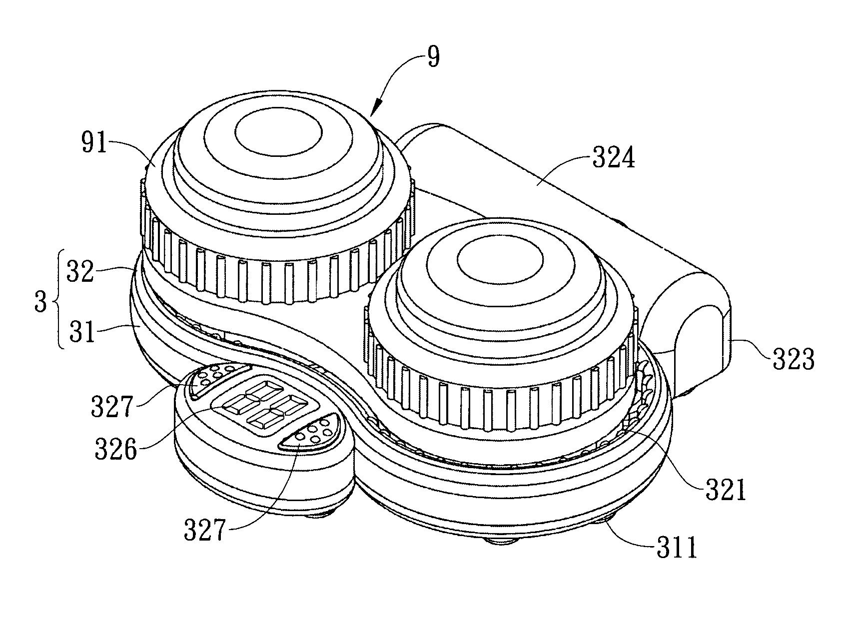
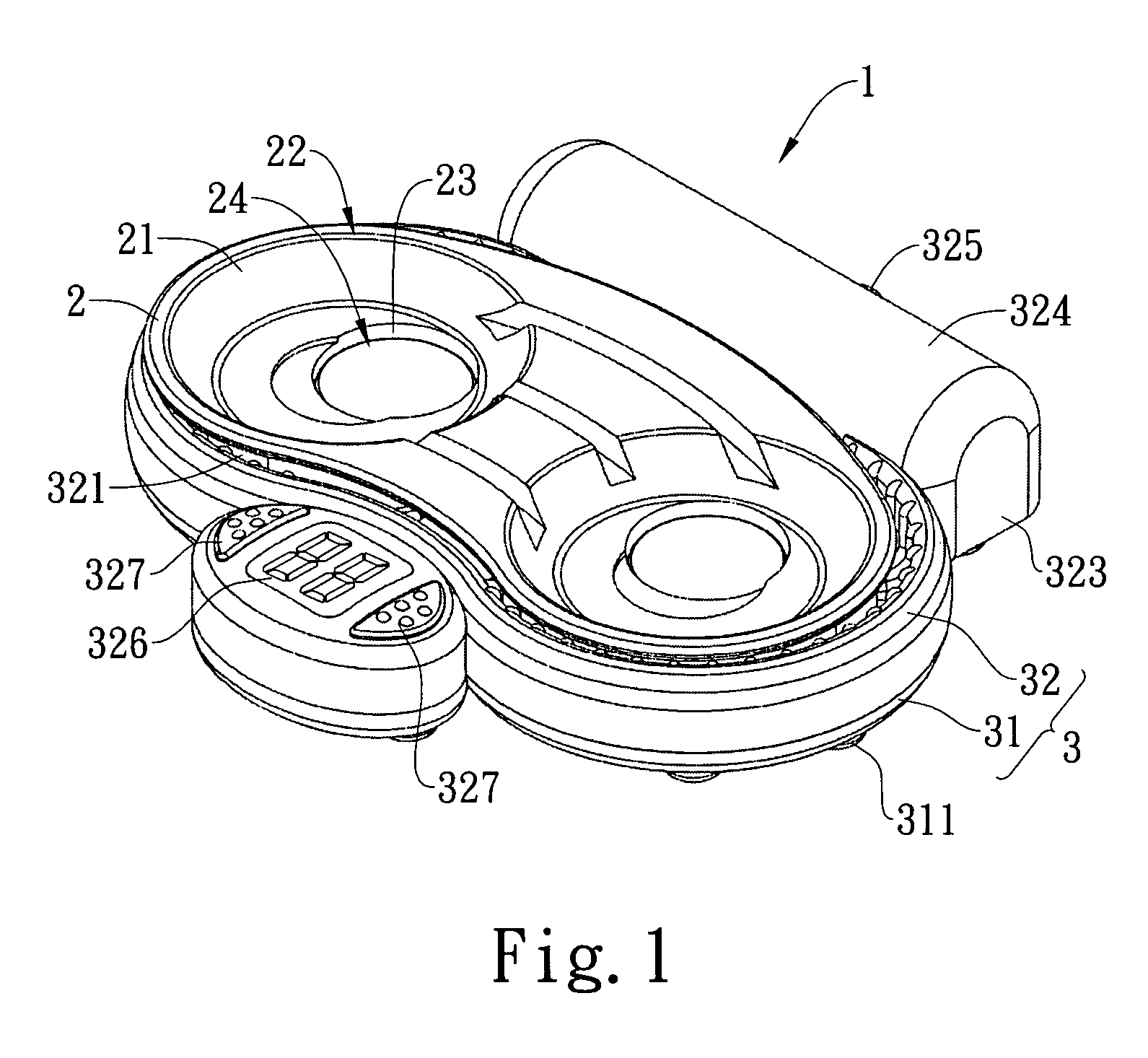
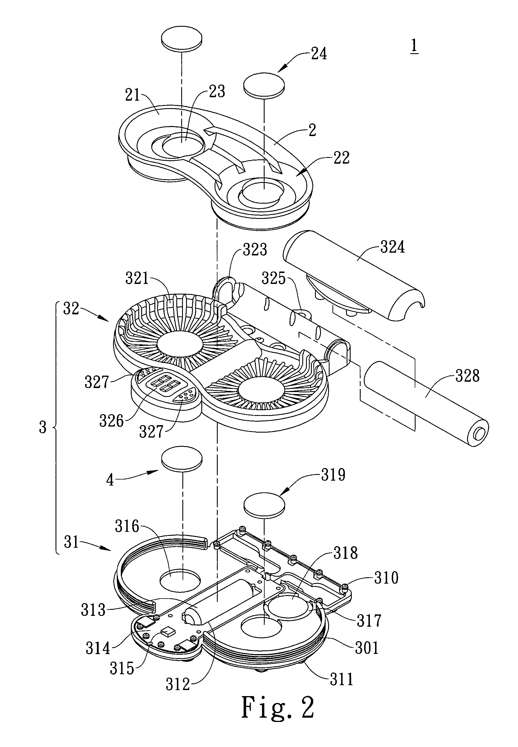
[0022]Please refer to FIGS. 1 and 2 that show a preferred embodiment of a vibration-type cleaning device 1 for contact lenses of the present invention. The vibration-type cleaning device 1 comprises an adaptor 2 and a base 3 and the adaptor 2 can support a contact lens case 9 thereon (as shown in FIG. 3).

[0023]The adaptor 2 is appropriately in flat shape. The left and right sides of the top of the adaptor 2 are provided respectively with a conical recess 21 and the two recesses form a support part 22. Each of the two recesses 21 has a bottom that is formed as a round recessed part 23 for placing and positioning a flat round magnet. The two magnets are used as a second magnetic piece 24. The left and right sides of the contact lens case 9 are provided respectively with a container 91. The two containers 91 are placed correspondingly into the two recesses 21 of the adaptor 2 and each container 91 is for containing clean solution and a contact lens. Besides, the bottom of the two conta...


PUM


Abstract

A vibration-type cleaning device for contact lenses comprises an adaptor that is provided with a support part thereon for supporting a contact lens case and a base that is provided under the bottom of the adaptor. The base is connected with the adapter via a positioning element so that the base can be attached to or detached from the adaptor. The base is provided with a vibrator therein and the vibrator is connected with a power source. Consequently, the vibrator can be driven under the control of a user to vibrate the contact lens solution and the contact lenses in the contact lens case and the cleaning effect of the contact lenses in the contact lens solution can be enhanced through vibration.

Description

BACKGROUND OF THE INVENTION[0001]1. Field of the Invention[0002]The present invention relates to a vibration-type cleaning device for contact lenses and, more particularly, to a vibration-type cleaning device for contact lenses comprising a base and an adaptor that can be attached to or detached from the base and is suitable for connection with contact lens cases of different specifications, where a vibrator is provided in the base for enhancing the cleaning effect of the contact lenses in the contact lens case and users can be reminded of the time when they have to dispose their contact lenses.[0003]2. Description of the Prior Art[0004]People with myopic problems usually wear glasses with frames in order to obtain normal or enough eyesight to maintain their normal vision performances. Recently, the glasses with frames are widely replaced by contact lenses under beauty consideration. However, corneas of users may suffer from anoxia that will cause injury to the corneas when people c...

Claims


Application Information

Patent Timeline
13 Sep 2011
Publication
US8015987B2
IPC
B08B3/04; B08B3/12; A45C11/00
CPC
A61L12/02; A61L12/026; Y10S134/901
Inventors
ZAKUTIN, DAVID MICHAEL