Lifting gear valve arrangement

a gear valve and gear arrangement technology, applied in the direction of fluid couplings, servomotors, couplings, etc., can solve the problem that the bearing pressure cannot be changed actively, and achieve the effect of minimal effor

Active Publication Date: 2011-09-20
BOSCH REXROTH AG
View PDF12 Cites 14 Cited by
  • Summary
  • Abstract
  • Description
  • Claims
  • Application Information

AI Technical Summary

Benefits of technology

[0011]As compared to this, it is an object of the invention to provide a lifting gear valve arrangement that enables the adjustment and limitation of a bearing pressure with minimum effort.
[0015]This lifting gear valve arrangement that is of very simple construction enables the bearing pressure to be adapted, by controlling the pressure limiting valve, to different operating conditions in an extremely simple and cost-efficient manner.

Problems solved by technology

With the conventional, single-action rear lifting gears, however, the bearing pressure cannot be changed actively since these lifting gears are not adapted to be operated in the field of work “pressing”.

Method used


Image

  • Lifting gear valve arrangement
  • Lifting gear valve arrangement
  • Lifting gear valve arrangement

Examples


Embodiment Construction

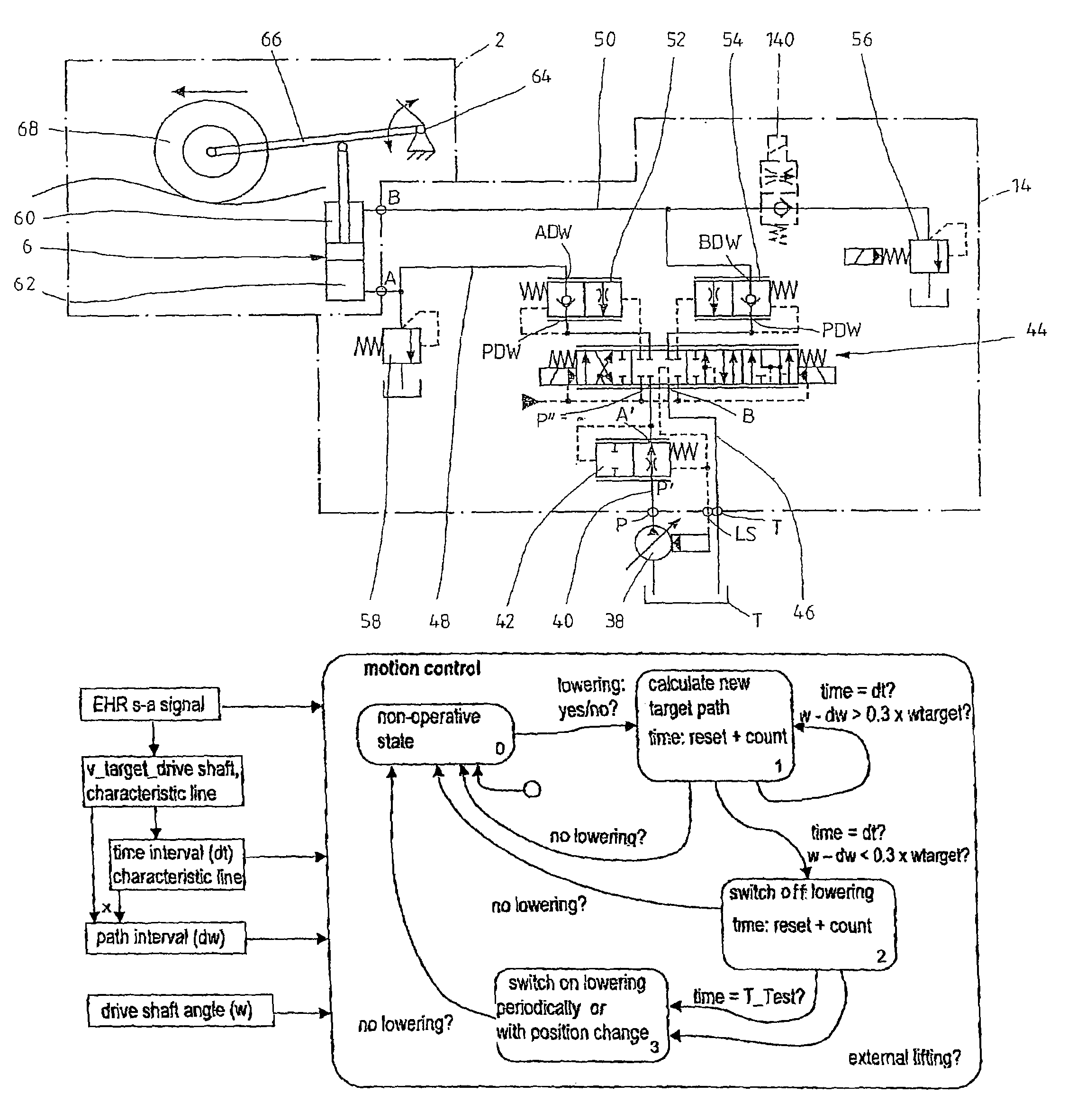
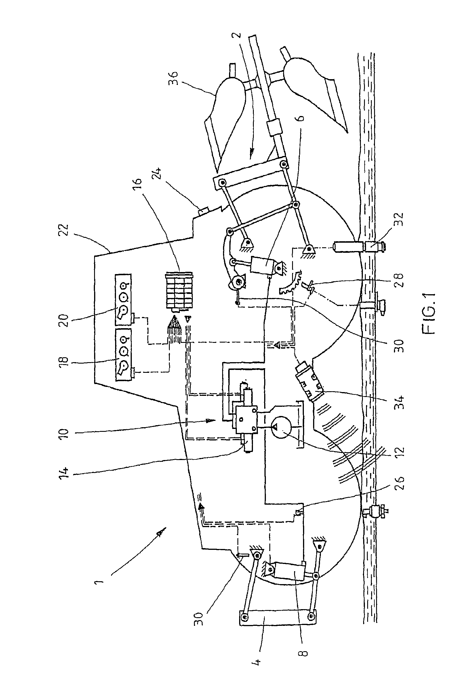
[0032]It is assumed that the tractor 1 illustrated in FIG. 1 comprises a double-action rear lifting gear 2 instead of a single-action one, wherein the pressure medium supply of the two pressure chambers of the lifting cylinder 6 is performed via an inventive lifting gear valve arrangement that is combined to form a control block 10 with the directional control valves for controlling the other loads of the tractor 1.

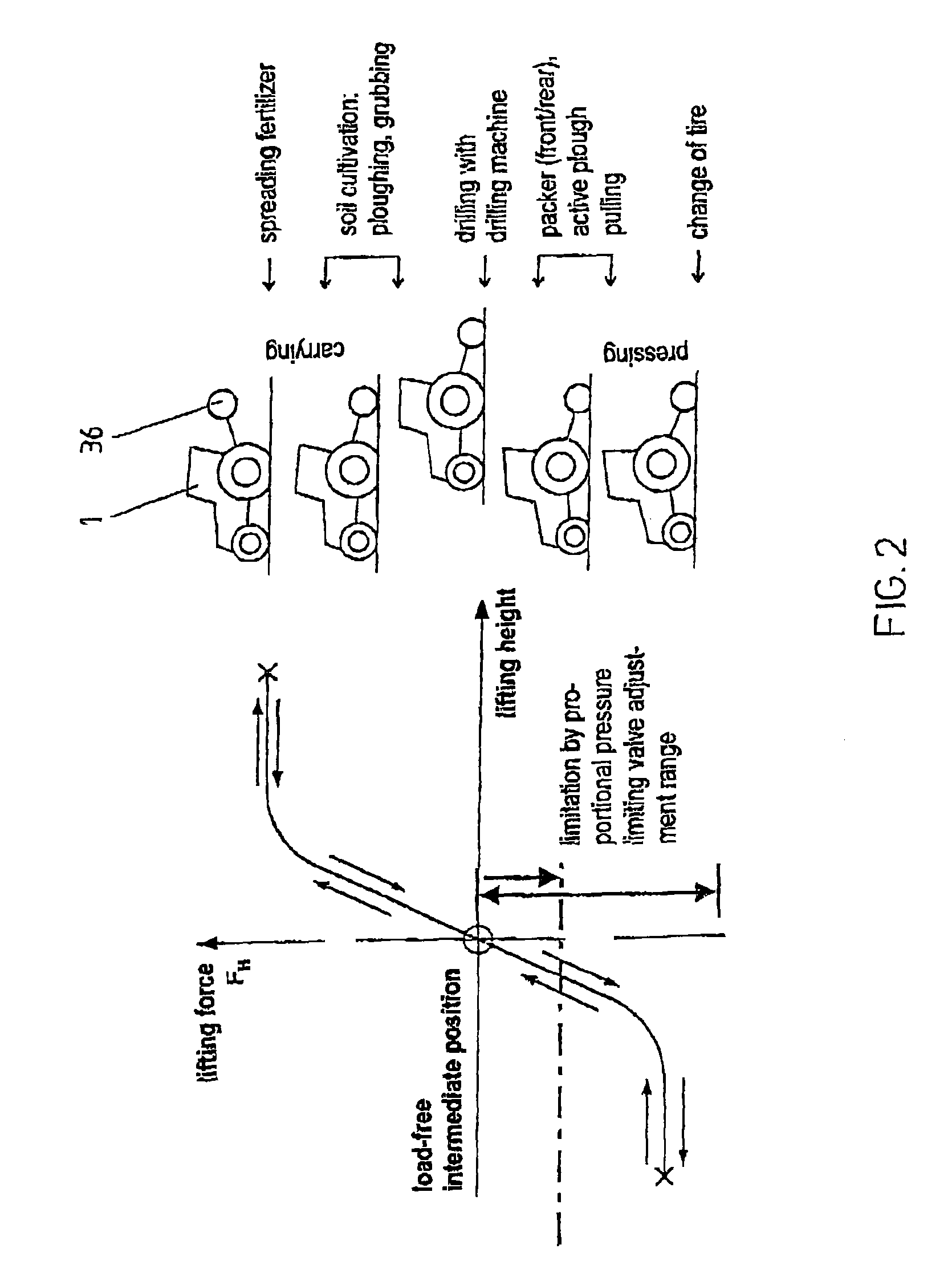
[0033]A rear lifting gear 2 in accordance with FIG. 1 can—as illustrated in FIG. 2—be used in different operating states. In the field of work “carrying”, the rear lifting gear and correspondingly add-on units 36 that are actuated by it, as the case may be, are either lifted off the ground or carried in ground contact with a predetermined support force. This field of work exists, for instance, during ploughing or during grubbing.

[0034]At the left of FIG. 2, the lifting force characteristics are represented in relation to the lifting height—this lifting force has to be exe...


PUM


Abstract

Disclosed is a lifting gear valve arrangement for controlling a double-action lifting gear or an add-on unit with a continuously adjustable directional control valve and with an individual pressure compensator via which a pressure medium volume flow to and from a lifting cylinder of the lifting gear can be controlled. A proportionally adjustable pressure limiting valve is provided in the pressure medium flow path between an outlet connection of the directional control valve and a working connection of the lifting gear valve arrangement, via which the pressure inside this area can be limited to a maximum value. The adjustment of the pressure limiting valve is preferably performed as a function of the operating states of the lifting gear or of the type of add-on unit.

Description

BACKGROUND OF THE INVENTION[0001]1. Field of the Invention[0002]The invention relates to a lifting gear valve arrangement for controlling a double-action lifting gear or an add-on unit of a mobile implement.[0003]2. Description of Related Art[0004]In modern tractors of the medium and upper performance classes, electrically controllable directional control valves have increasingly been used in work hydraulics for controlling the work functions of coupled devices. The control of these hydraulic functions is performed via a very compact control block in which the control is combined to form a unit along with all the essential directional control valves and regulating valves. Such a control block is, for instance, described in the catalogue 1 987 760 507 (electronic-hydraulic lifting gear regulation for tractors) by the Applicant.[0005]FIG. 1, which is referred to now already, illustrates the basic structure of the work hydraulics of a tractor 1 or of some other mobile implement. In acc...

Claims


Application Information

Patent Timeline
Patent Type & Authority Patents(United States)
IPC IPC(8): F15B11/028
CPCE02F9/2225F15B11/028F15B11/05F15B11/15F15B13/0417F15B2211/20553F15B2211/30535F15B2211/30545F15B2211/3111F15B2211/327F15B2211/329F15B2211/50518F15B2211/50536F15B2211/5153F15B2211/526F15B2211/528F15B2211/55F15B2211/57F15B2211/6051F15B2211/63F15B2211/6653F15B2211/7053E02F9/2203E02F9/2228E02F9/2296
Inventor JESSEN, SOENKEKEUPER, GERHARDLOEDIGE, HEINRICHKUNZ, REINER
Owner BOSCH REXROTH AG
Why Eureka
Try Eureka