Golf club shaft

a golf club and shaft technology, applied in the field of golf club shafts, can solve the problems of deteriorating the directivity of hit balls, and achieve the effects of accelerating the head speed, large flexure amount, and large flexur

Active Publication Date: 2011-09-20
SUMITOMO RUBBER IND LTD
View PDF8 Cites 14 Cited by
  • Summary
  • Abstract
  • Description
  • Claims
  • Application Information

AI Technical Summary

Benefits of technology

[0009]The present inventor has examined the flexural rigidity distribution of the shaft based on a technical idea different from the conventional technique. The behavior of the shaft during the swing has been examined. As a result, the flexural rigidity distribution of the shaft was found to have a room for the improvement. The shaft of the present invention was found to tend to obtain a large flexure amount and to tend to release the flexure. This shaft tends to obtain a large flexure and to release this flexure. The release of the large flexure accelerates a head speed. This shaft tends to obtain a large head speed. The large head speed contributes to the increase in a flight distance.
[0010]The insufficient release of the flexure is apt to deteriorate the directivity of hit balls. When the release of the flexure is insufficient, a face of the shaft is apt to be opened at impact. Since the shaft of the present invention tends to release the flexure, the shaft can improve the directivity of the hit ball.

Problems solved by technology

The insufficient release of the flexure is apt to deteriorate the directivity of hit balls.

Method used


Image

  • Golf club shaft
  • Golf club shaft
  • Golf club shaft

Examples


example 1

[0095]A shaft was produced by a sheet winding method. A plurality of prepregs were wrapped around a metal mandrel to be laminated. The developed view of the laminated prepregs is shown in FIG. 3. Nine prepregs were wrapped around the mandrel (not shown) in order of a prepreg s1, a prepreg s2, . . . , a prepreg s9. The prepreg shown on a higher side in FIG. 3 was laminated on the inner side.

[0096]The prepreg s1 is a layer which reinforces a tip part of the shaft. In the prepreg s1, the orientation angle of a fiber is substantially 0 degree to the axial line of the shaft. That is, the prepreg s1 constitutes a straight layer. The prepreg s2 is provided over the full length of the shaft. The prepreg s2 is so-called a bias layer. In the prepreg s2, the orientation angle of a fiber is substantially −45 degrees to the axial line of the shaft. A prepreg s3 is also provided over the full length of the shaft. The prepreg s3 is so-called a bias layer. In the prepreg s3, the orientation angle o...

example 2

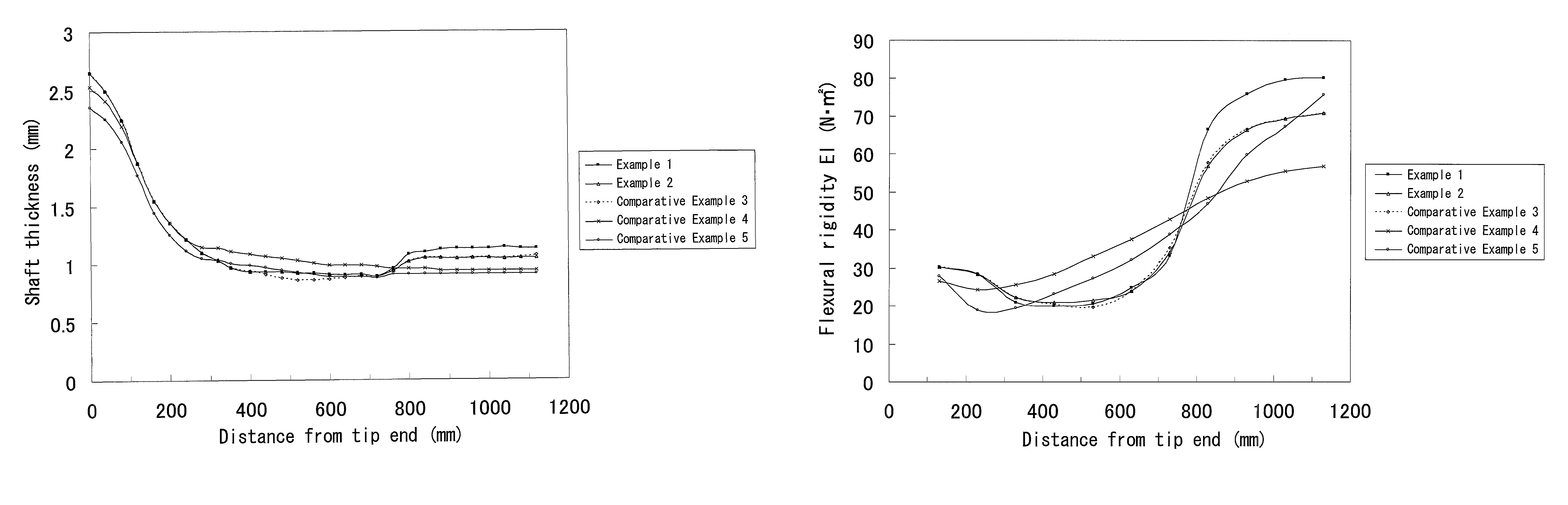
[0099]The developed view of a shaft of Example 2 is shown in FIG. 4. In Example 2, nine prepregs e1 to e9 were used. The varieties of the prepregs of Example 2 are shown in Table 2. A shaft and a golf club according to Example 2 were obtained in the same manner as in Example 1 except that the compositions of the prepregs shown in FIG. 4 and Table 2 were used. Even in Example 2, the shaft was subjected to surface polishing so as that a point separated by 720 mm from a tip Tp of the shaft was a thinnest part.


PUM


Abstract

A shaft 6, which is a tubular body, includes a laminate of fiber reinforced resin layers. This fiber reinforced resin layer includes a matrix resin and a fiber. When a portion with a minimum thickness in the entire shaft is defined as a thinnest part, the entire thinnest part exists in a range of a first position to a second position. The first position is a position where an axial distance from a tip of the shaft is 50% of a full length of the shaft. The second position is a position where the axial distance from the tip of the shaft is 75% of the full length of the shaft. In this shaft 6, a flexural rigidity value EIc (N / m2) of the shaft at a point which is 175 mm away from a rear end of the shaft is two times or greater and three times or less of a flexural rigidity value EIm (N / m2) of the thinnest part.

Description

[0001]The present application claims priorities on Japanese Patent Application No. 2008-190598 filed on Jul. 24, 2008. The whole contents of the Japanese Patent Application are hereby incorporated by reference.BACKGROUND OF THE INVENTION[0002]1. Field of the Invention[0003]The present invention relates to a golf club shaft.[0004]2. Description of the Related Art[0005]A golf club shaft flexes during a swing. In particular, in the early stage of a downswing, the flexure of the shaft is caused by the inertia of a head. The shaft flexes so as that the head delays relative to the travel direction of the downswing in the early stage of the downswing. The angular acceleration of the shaft decreases gradually from the downswing to the impact to release the flexure of the shaft. This release of the flexure accelerates the speed of the head to obtain a large flight distance.[0006]The shaft has a flexural rigidity distribution. The flexural rigidity distribution influences the flexure during t...

Claims


Application Information

Patent Timeline
Patent Type & Authority Patents(United States)
IPC IPC(8): A63B53/10A63B102/32
CPCA63B53/10A63B59/0014A63B2209/023A63B60/10A63B60/06A63B60/08A63B60/46A63B60/0081
Inventor KATO, MASATOSHI
Owner SUMITOMO RUBBER IND LTD
Why Eureka
Try Eureka