Lens drive device

a drive device and lens technology, applied in the direction of dynamo-electric components, dynamo-electric machines, instruments, etc., can solve the problems of metal springs, metal fatigue or permanent deformation, easy vibration of the lens, etc., and achieve the effect of reducing its siz

Inactive Publication Date: 2011-08-23
SANKYO SEIKI MFG CO LTD
View PDF11 Cites 0 Cited by
  • Summary
  • Abstract
  • Description
  • Claims
  • Application Information

AI Technical Summary

Benefits of technology

[0017]In view of the problems described above, at least an embodiment of the present invention may advantageously provide a lens drive device which is capable of reducing its size while assuring its shock resistant property.
[0025]In the conventional lens drive device, in order to press the movable body against the support body, an urging force by the restricting member which is larger than the weight of the entire movable body is required (“W<F1” or “W<F2”). In this case, the restricting member is resiliently bent toward the non-energized position side in order to press the movable body against the support body to maintain the non-energized position and, when the coil is energized, the restricting member is resiliently bent toward the energized position which is an opposite to the non-energized position and thus its bending amount when the coil is energized becomes larger as described above. Therefore, when the size of the lens drive device is further reduced, the restricting member may easily occur a fatigue failure. However, in the lens drive device in accordance with at least an embodiment of the present invention, the following relationships are satisfied: W>F1, W>F2, and W<F1+F2
[0026]Therefore, an urging force larger than the weight of the entire movable body is not required in the restricting member by providing a magnetic member. Accordingly, the restricting member can be prevented from being resiliently bent larger when the coil is not energized and thus fatigue failure of the restricting member can be prevented.

Problems solved by technology

In other words, in a state where a cell phone is not used, a drive mechanism for moving a lens is not operated and thus the lens is easily vibrated due to a shake or an impact.
As a result, the lens is easily displaced or damaged by the shake or the impact.
Therefore, the metal spring may occur metal fatigue or permanent deformation.
In addition, when the plate spring 105 has been continuously used at the spring deflection limit value or its vicinity of metal material of the plate spring 105, fatigue failure is likely to occur to the plate spring 105.
Especially, according to miniaturization demand for an actuator in recent years, when the plate spring 105 is made further smaller or thinner, the strength of the plate spring 105 becomes weaker or the plate spring 105 becomes easily to bend and thus fatigue failure may occur.

Method used


Image

  • Lens drive device
  • Lens drive device
  • Lens drive device

Examples


Embodiment Construction

[0034]An embodiment of the present invention will be described below with reference to the accompanying drawings.

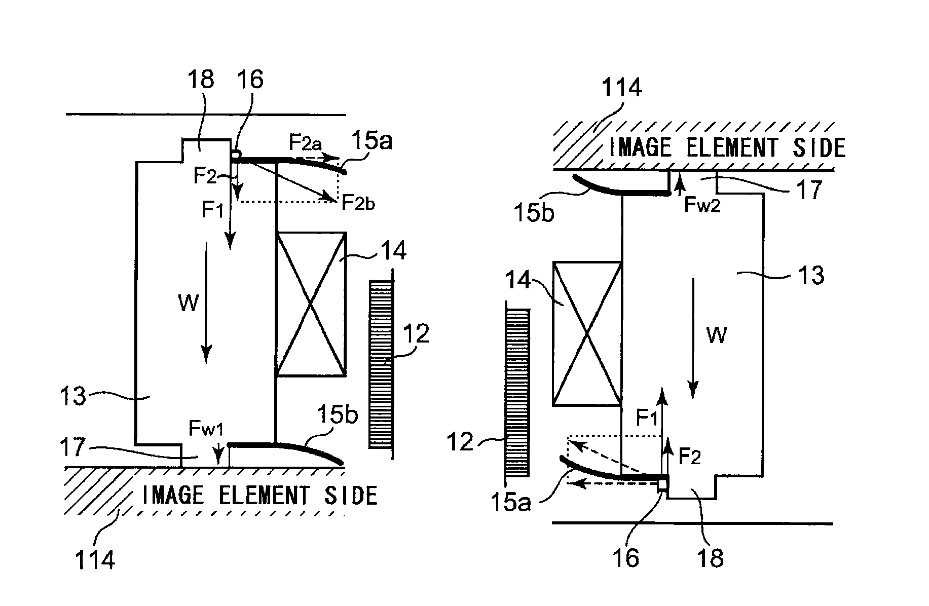
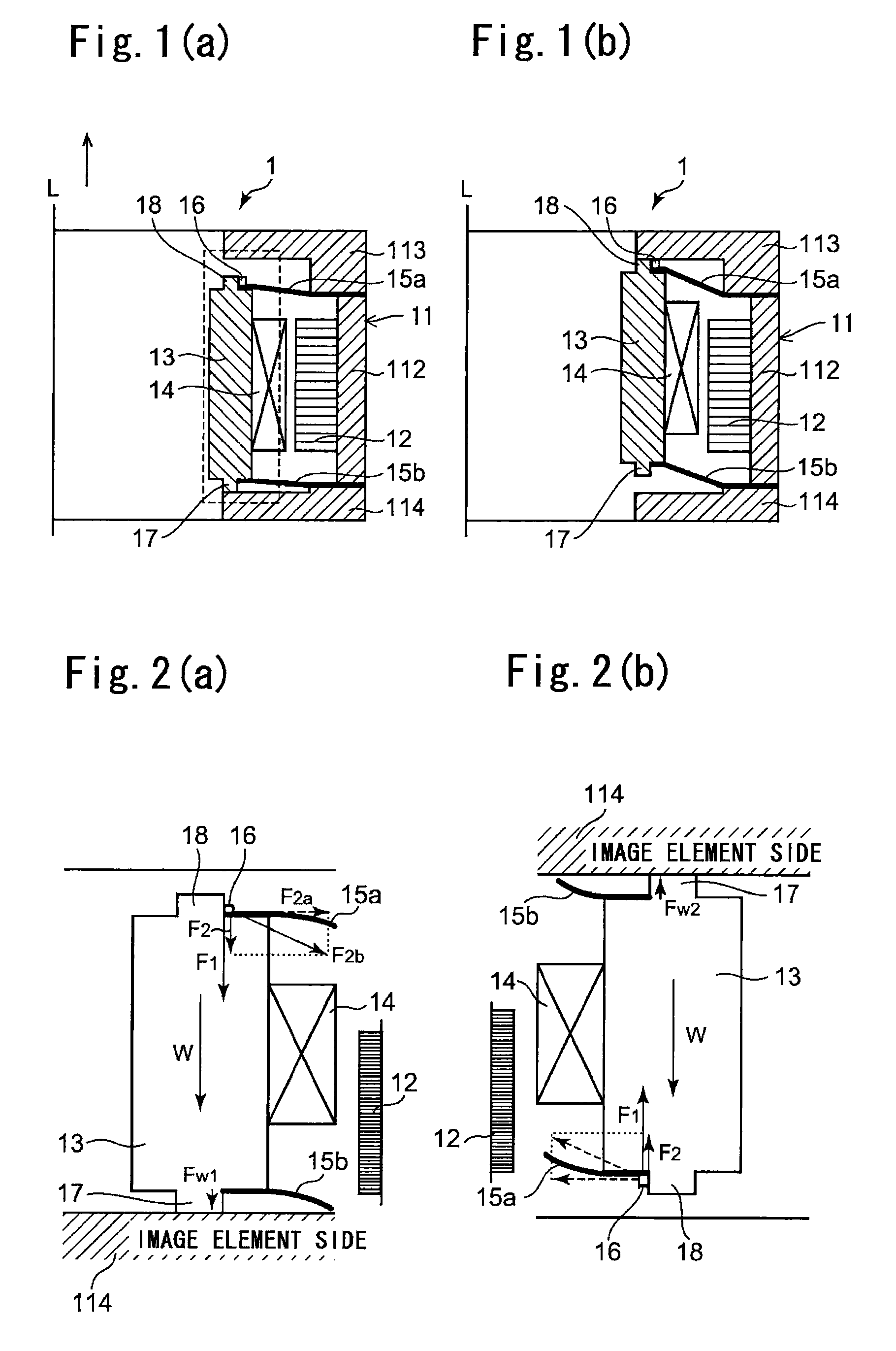
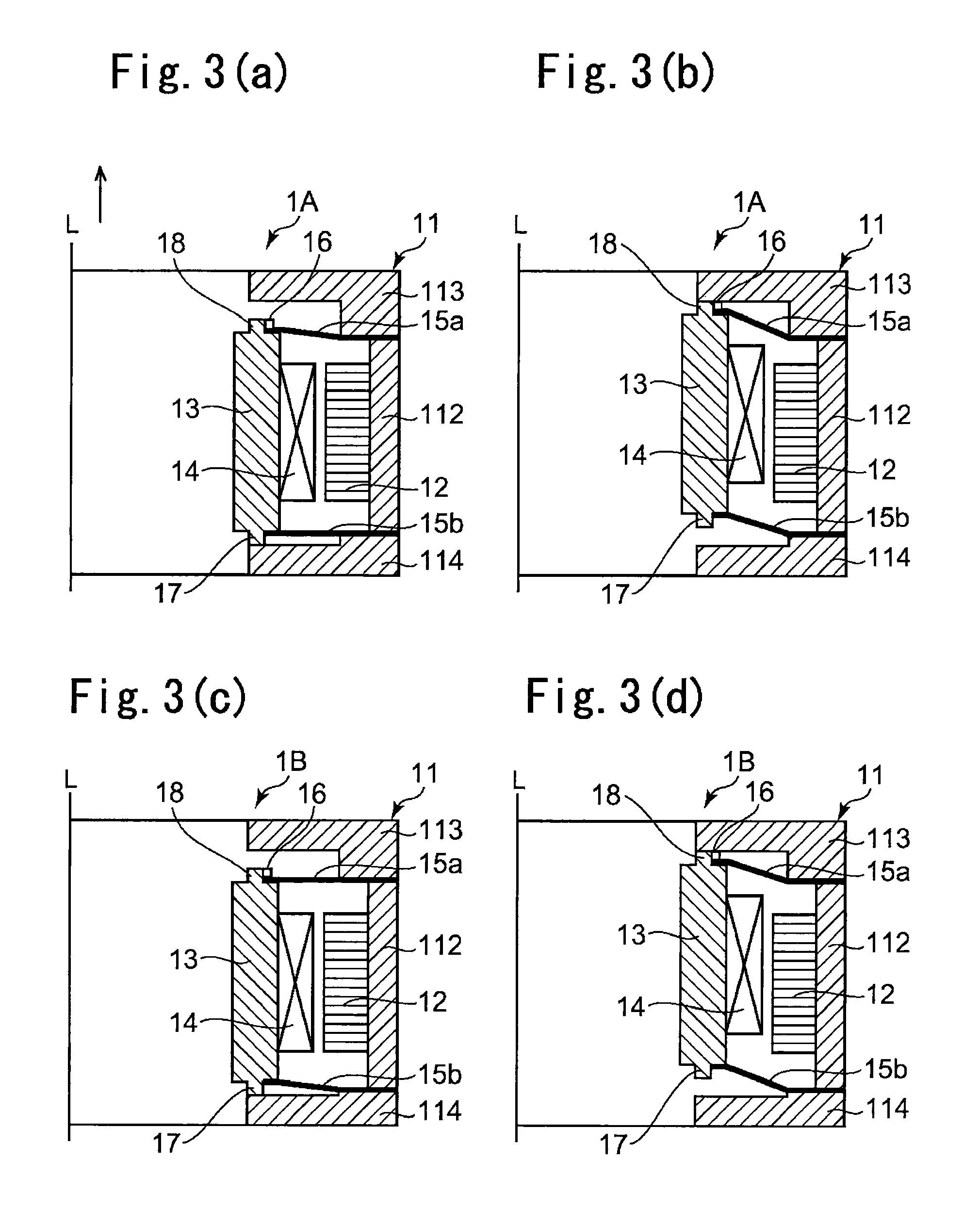
[0035]FIGS. 1(a) and 1(b) are cross sectional schematic views showing a right half side of a lens drive device 1 in accordance with an embodiment of the present invention. In the lens drive device 1, FIG. 1(a) is a view showing a state where a coil 14 is not energized, in other words, a sleeve 13 is located at a normal photographing position, i.e., at a non-energized position. FIG. 1(b) is a view showing a state where the coil 14 is energized, in other words, the sleeve 13 is located at a close-up photographing position, i.e., at an energized position in the lens drive device 1. Detail description of the entire structure of the lens drive device 1 is omitted because a well-known lens drive device may be applied to this embodiment. Further, FIGS. 1(a) and 1(b) show only a right half side with respect to the optical axis “L” of a lens when the lens drive device 1 is cut lon...


PUM


Abstract

A lens drive device may include a movable body having a lens and a coil, a support body movably supporting the movable body, a magnetic drive mechanism having a magnet for driving the movable body together with the coil, a restricting member for restricting movement of the movable body due to an electromagnetic force generated when an electric current is supplied to the coil, a magnetic member disposed in the movable body to be magnetically attracted by the magnet. In a non-energized state where the coil is not energized, following relationships are satisfied:W>F1, W>F2, and W<F1+F2. wherein a force with which the restricting member urges the movable body toward a non-energized position is “F1”; a force in the optical axis direction with which the magnetic member is attracted by the magnet is “F2”; and a weight of the entire movable body is “W”.

Description

CROSS REFERENCE TO RELATED APPLICATION[0001]The present invention claims priority under 35 U.S.C. §119 to Japanese Application No. 2007-249916 filed Sep. 26, 2007 the entire contents of which are incorporated herein by reference.FIELD OF THE INVENTION[0002]At least an embodiment of the present invention may relate to a lens drive device in which a lens is driven to move in an optical axis direction for forming an image of an object to be photographed.BACKGROUND OF THE INVENTION[0003]As cell phones with cameras in which a camera is mounted have become popular in recent years, chances photographing various objects to be photographed by using the cell phone have increased. For example, there is a case that an object such as a friend or landscape which is apart from a lens of a camera to some extent is photographed (normal photographing) and, alternatively, there is a case that an object such as a timetable for bus or petals of a flower at a position near the lens of the camera is photo...

Claims


Application Information

Patent Timeline
Patent Type & Authority Patents(United States)
IPC IPC(8): G02B7/02
CPCG02B13/001H02K33/18H02K41/0356G02B7/08
Inventor FURUYA, YUKIOOOTSUKI, NOBORU
Owner SANKYO SEIKI MFG CO LTD
Why Eureka
Try Eureka