
Warning apparatus for a motor vehicle

a technology for warning apparatus and motor vehicles, applied in the direction of anti-theft devices, instruments, transportation and packaging, etc., can solve the problems of blind angle, inability to completely eliminate, and inability to react to errors made by others, and achieve the effect of simple design

Inactive Publication Date: 2011-09-20
FORD GLOBAL TECH LLC
View PDF15 Cites 213 Cited by
  • Summary
  • Abstract
  • Description
  • Claims
  • Application Information

AI Technical Summary

Benefits of technology

The present invention provides a warning apparatus for a motor vehicle that can monitor the blind spot and is simple and easy to use. The driver does not need to learn any new system or make major changes to their driving habits. The signal display is connected to the sensor system and can display a visual warning signal in the driver's field of view. The display can have separate areas for the left and right lanes, and can also flash in a rapid sequence to improve visual alertness. The visual and auditory signals can be generated in different intervals and can be synchronized. The signal display can also be surrounded or encompassed by an illumination system for added visual impact. The invention can be used with a lane change assistant for monitoring the extended, rear area of the vehicle.

Problems solved by technology

This blind spot area varies in size depending on the number of windows and rearview mirrors and cannot be completely eliminated.
One particular problem is the blind angle in the case of trucks, buses and motorcycles since these only have a restricted radius of view due to the size and design.
It is also impossible to react to errors made by others in the blind angle, as a result of which accidents also occur.
Moreover, the acoustic warning has the disadvantage that it is not equally suitable in all driving situations and in the case of all drivers and cannot indicate the direction in which the detected vehicle lies.
This apparatus is, however, relatively complex and can only warn the driver when he leaves his or her hand on the turn indicator control for a sufficiently long time.
The blind spot can only be insufficiently monitored with this apparatus since the identified or detected obstacle must be visible in the mirror.

Method used


Image

  • Warning apparatus for a motor vehicle
  • Warning apparatus for a motor vehicle
  • Warning apparatus for a motor vehicle

Examples


Embodiment Construction

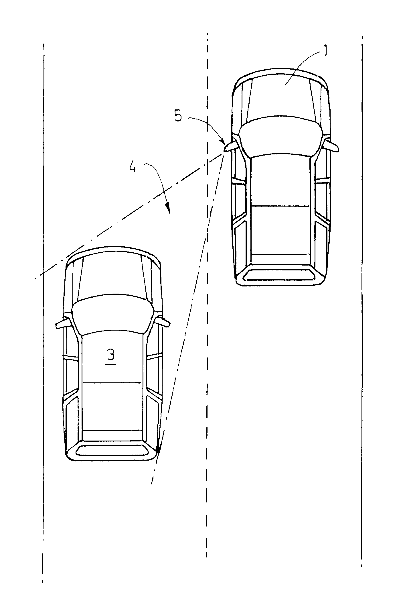
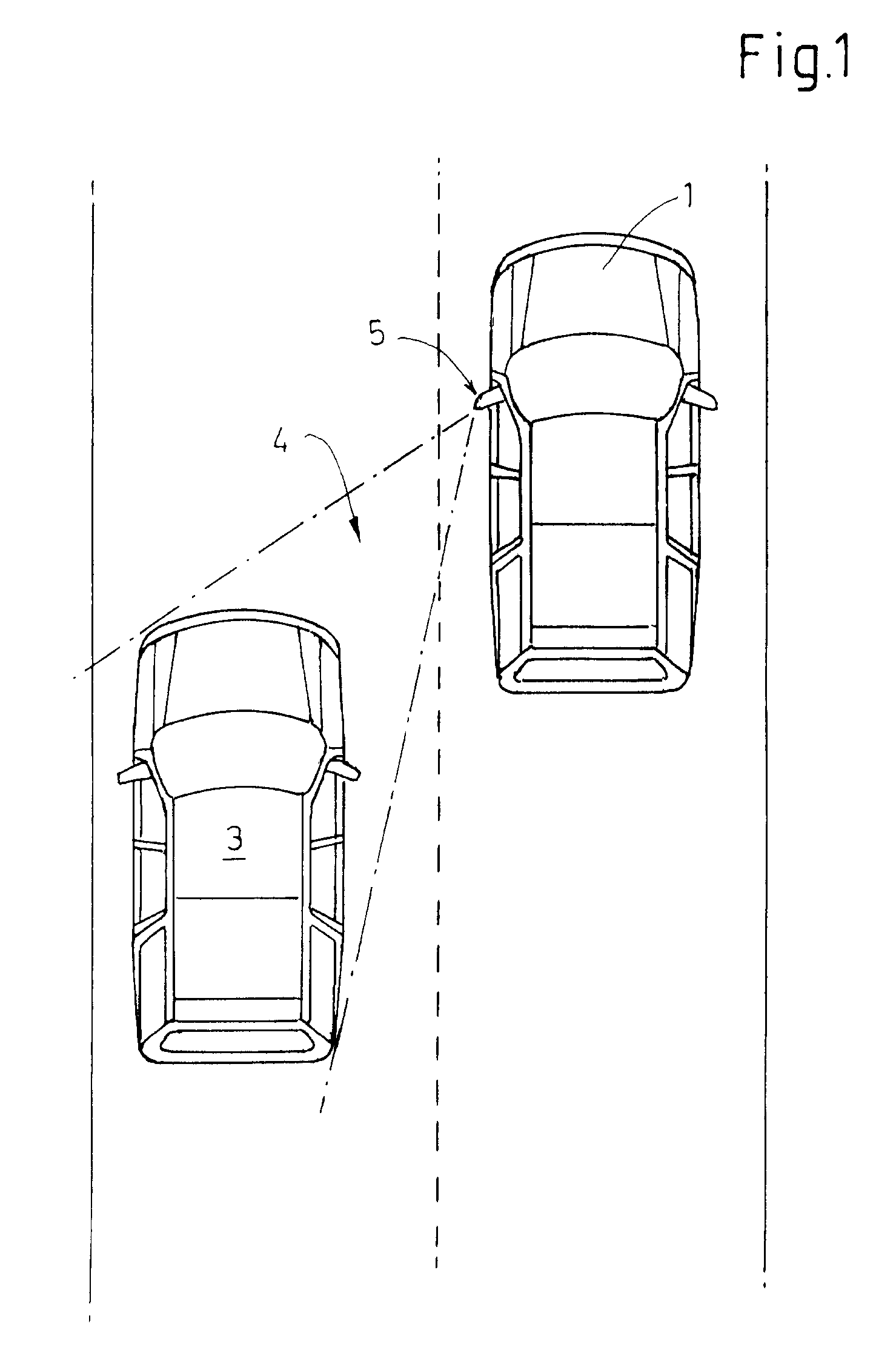
[0028]FIG. 1 illustrates by way of example a vehicle 1 which is provided with a warning apparatus 2 which informs or warns the driver of the vehicle when a second vehicle 3 enters into blind spot 4.

[0029]Blind spot 4 is the area into which sideview mirror 5 does not allow a view without the movement of the driver. Blind spot 4 can be of various forms and sizes depending on the vehicle, mirror configuration, etc.

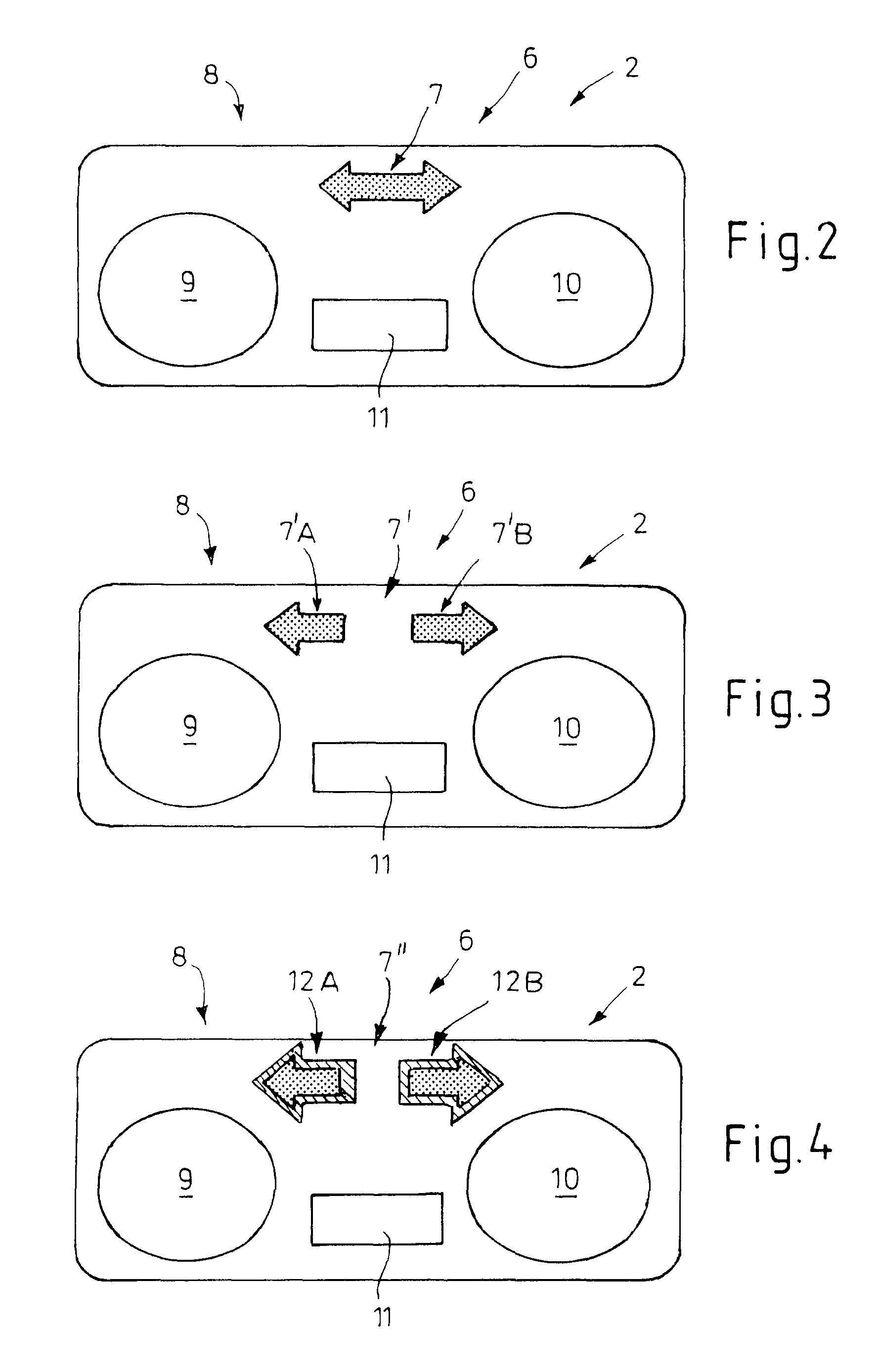
[0030]Various embodiments of warning apparatus 2 are represented in the further figures. These embodiments are discussed below jointly with reference to identical reference numbers, with the differences being discussed in detail.

[0031]Vehicle 1 provided with a warning apparatus 2 comprises in each case an indicator system 6 for displaying a lane change, indicator system 6 having a signal display 7 arranged in the field of view of the driver.

[0032]In the present case, signal display 6 is arranged in a prominent position in central instrument panel 8 of the dashboard of the veh...


PUM


Abstract

Warning apparatus (2) for a motor vehicle (1) having an indicator system (6) for indicating a change of lane comprising at least one signal display (7) arranged in the field of view of the driver and having a sensor system for detecting obstacles in the blind spot (4), wherein the sensor system generates a warning signal in the event of detection of an obstacle, wherein the signal display (7) of the indicator system (6) is connected to the sensor system such that the warning signal is reproduced in visual form via the signal display (7).

Description

FIELD OF THE INVENTION[0001]The invention relates to a warning apparatus for a motor vehicle having an indicator system for indicating a change of lane comprising at least one signal display arranged in the field of view of the driver and having a sensor system for detecting obstacles in the blind spot, wherein the sensor system generates a warning signal in the event of detection of an obstacle.BACKGROUND OF THE INVENTION[0002]Monitoring of the blind spot is an important and difficult task for drivers of a motor vehicle in order to prevent accidents. The blind spot is the area to the side of and behind motor vehicles which the driver cannot be easily see by means of the sideview and rearview mirrors or without significant body movements.[0003]This blind spot area varies in size depending on the number of windows and rearview mirrors and cannot be completely eliminated. One particular problem is the blind angle in the case of trucks, buses and motorcycles since these only have a res...

Claims


Application Information

Patent Timeline
Patent Type & Authority Patents(United States)
IPC IPC(8): B60Q1/00
CPCB60Q9/008
Inventor LA TENDRESSE, INGOMUELLER, HOLGER
Owner FORD GLOBAL TECH LLC
Learn More