Eureka AIR delivers breakthrough ideas for toughest innovation challenges, trusted by R&D personnel around the world.

Vehicle workstation

Active Publication Date: 2011-09-27
KENNEDY SR MARK B
View PDF31 Cites 9 Cited by
  • Summary
  • Abstract
  • Description
  • Claims
  • Application Information

AI Technical Summary

Benefits of technology

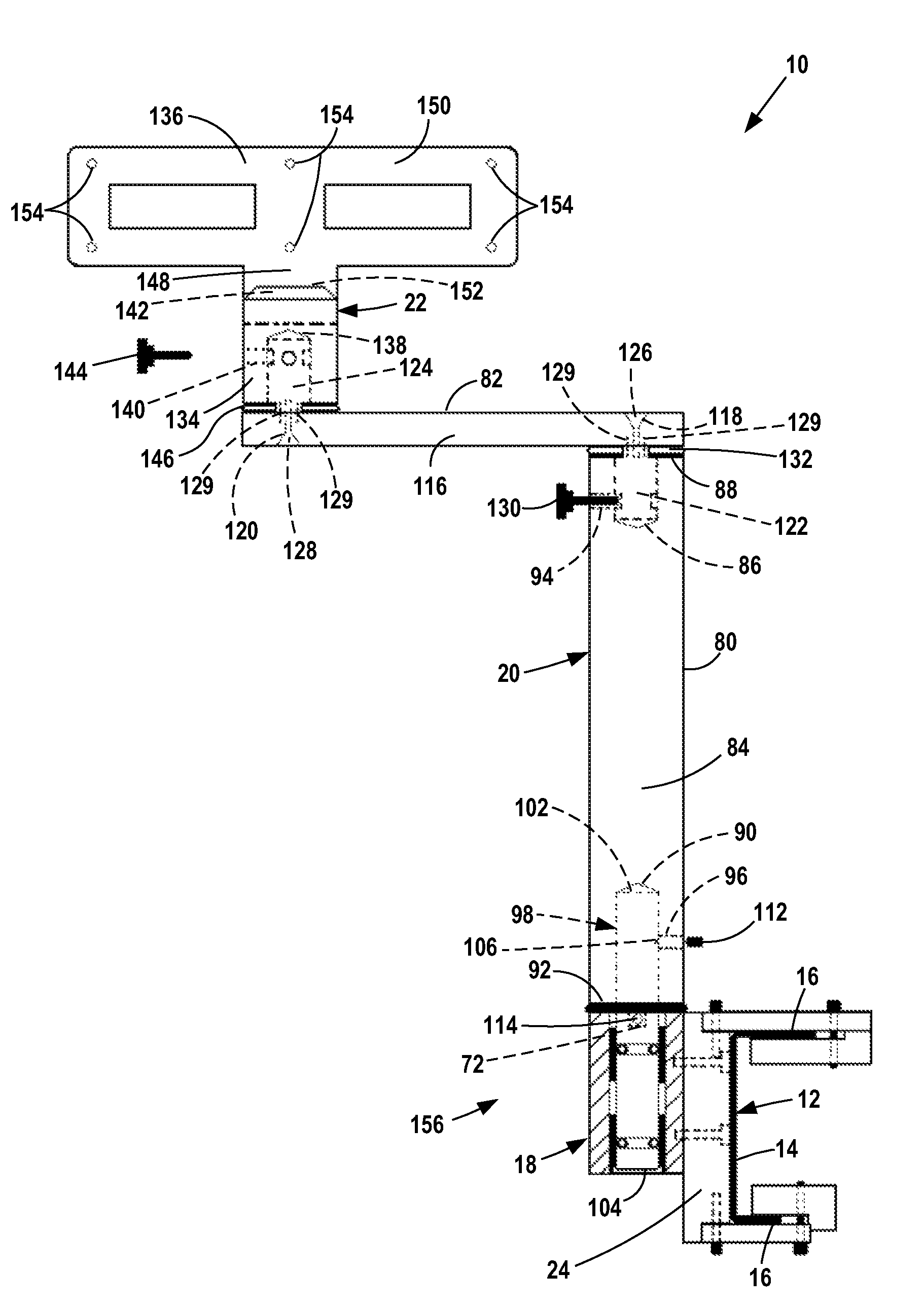
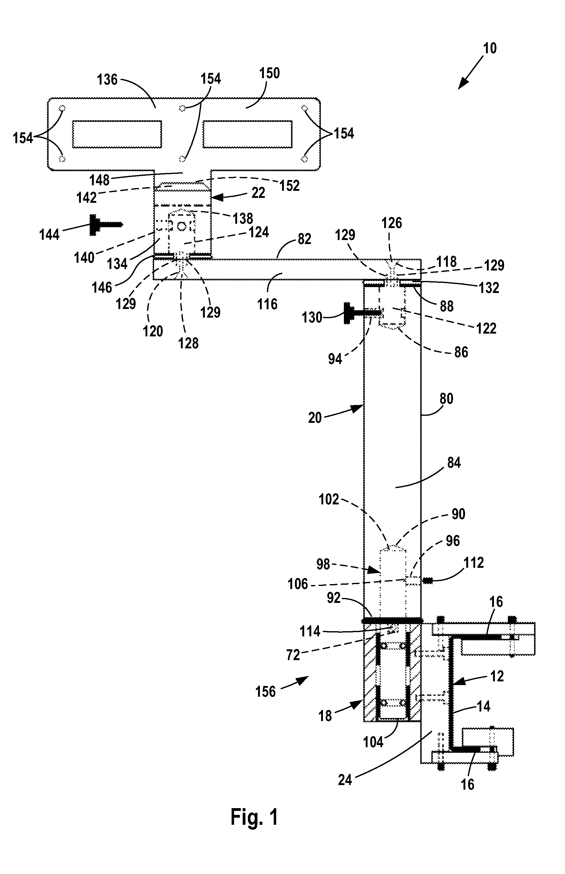
[0007]The invention is a vehicle workstation for mounting display equipment in a vehicle, preferably on the passenger-side of the vehicle across from the driver. The workstation is easily attached to and removed from existing vehicle fixtures, does not require permanent alteration to the vehicle interior for attachment and includes a shock absorber assembly which isolates the display equipment mounted on the workstation from vehicle vibrations and jolts to permit the driver to view the display equipment despite vibrations and jolts.
[0008]The workstation includes a base that is attached to the interior of the vehicle and one or more support members extending from the base to an equipment support plate. A shock absorber assembly is located between adjacent rigid workstation members to prevent transmission of vehicle vibrations and jolts along the support members to the equipment support plate. The size of the support members can be adjusted to meet specific vehicle dimensions and user needs.
[0009]In one embodiment, the workstation base includes a clamp assembly adapted to engage a portion of a seat on the passenger side of the vehicle. If a passenger needs to ride in the passenger side seat, the support members are easily removed from the base and the seat may be used while the base remains mounted to the seat. The clamp assembly allows workstation mounting without drilling holes or making other permanent alterations to the vehicle interior.
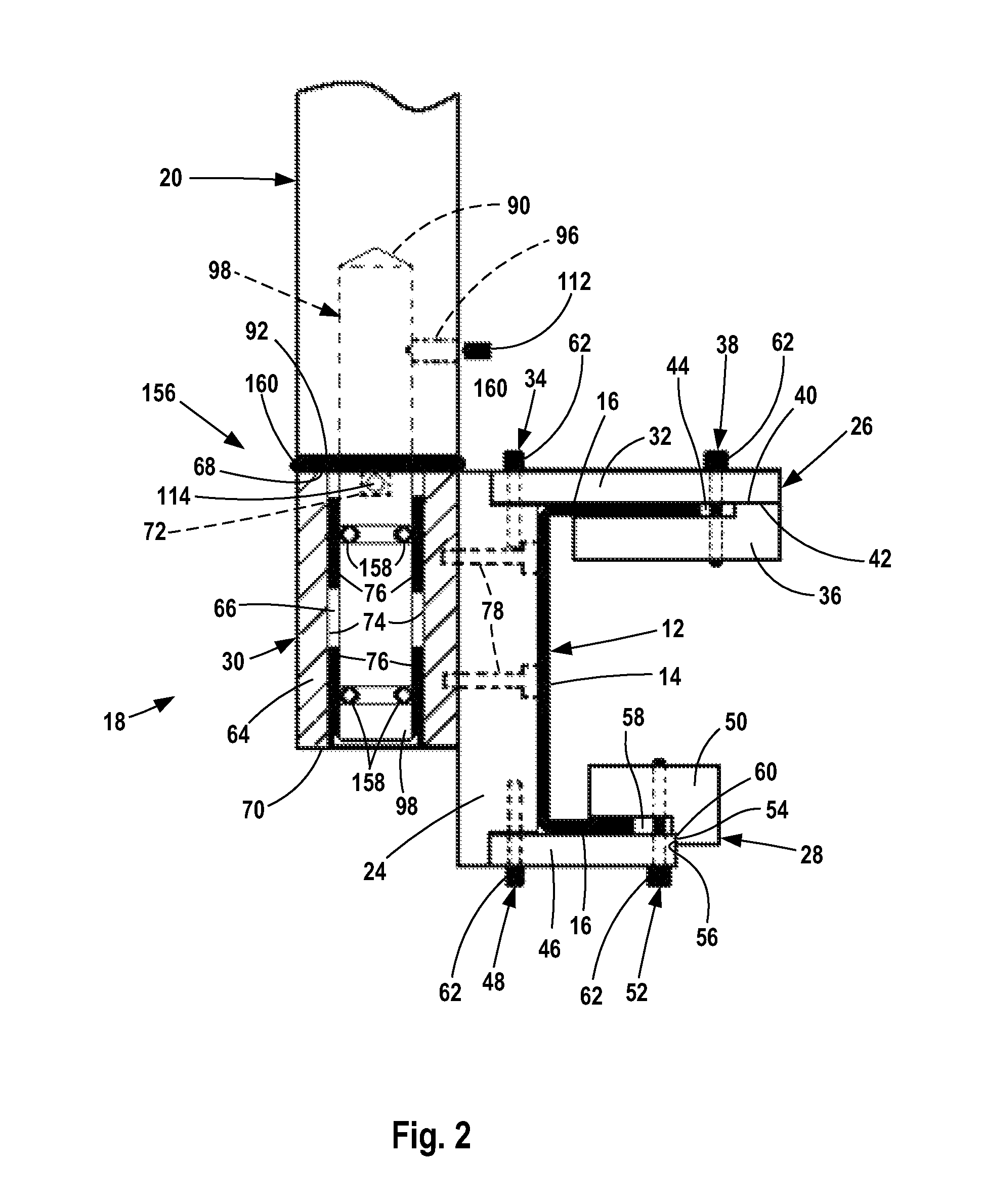
[0010]The base includes a base sleeve into which a shaft extending downward from a lower support member is extended. The shock absorber assembly is located between the base sleeve and the mounting shaft to reduce or prevent metal-to-metal contact between the sleeve and the mounting shaft. This greatly dampens or prevents the transmission of vibrations and jolts between the workstation members and isolates the equipment support plate and equipment on the plate from vibrations and shocks.

Problems solved by technology

This greatly dampens or prevents the transmission of vibrations and jolts between the workstation members and isolates the equipment support plate and equipment on the plate from vibrations and shocks.

Method used


Image

  • Vehicle workstation
  • Vehicle workstation
  • Vehicle workstation

Examples


Embodiment Construction

[0023]Vehicle workstation 10 is mounted to an internal vehicle fixture, such as a seat rail 12. Seat rail 12 is a thin, elongate rail that is part of the external metal framing found in conventional “air-ride” type seats.

[0024]Seat rail 12 has a body 14 that extends generally perpendicularly to the floor of the vehicle and one or two arms 16 that extend generally parallel to the floor of the vehicle so that the rail body and arms form a generally C-shape in two-arm variants or a generally L-shape in one-arm variants as illustrated in FIGS. 5 and 8.

[0025]Alternatively, the workstation can be mounted to other like internal vehicle fixtures.

[0026]Vehicle workstation 10 includes a mounting base 18, a support assembly 20 joined to the base and equipment support plate 22 joined to the support assembly.

[0027]Mounting base 18 has a body 24, top and bottom clamp assemblies 26 and 28 on one side of the body and a mounting member 30 on the other side of the body.

[0028]Top clamp assembly 26 has...


PUM


Abstract

A vehicle workstation for mounting laptop computers and other equipment inside a vehicle that is easily attached to and removed from the vehicle and prevents vehicle vibrations and jolts from being transmitted to the equipment.

Description

FIELD OF THE INVENTION[0001]The invention relates to workstations mounted in vehicles for supporting laptop computers and other equipment for use by the vehicle operator.BACKGROUND OF THE INVENTION[0002]Vehicle workstations are commonly used in delivery trucks to allow drivers to keep track of delivery routes, in police vehicles to allow officers access to electronic records and in other vehicles for like applications.[0003]Conventional vehicle workstations include a base mounted to a vehicle dashboard or other internal vehicle fixture and one or more position-adjustable support members extending from the base to an equipment support plate on which display equipment is mounted. The workstation is usually mounted on the passenger side of a vehicle next to the driver.[0004]A common problem with conventional workstations is that jolts and vibrations generated during vehicle operation are transmitted from the vehicle to the display equipment. The vibrations make it difficult for an oper...

Claims


Application Information

Patent Timeline
Patent Type & Authority Patents(United States)
IPC IPC(8): A47B23/00
CPCB60R11/0252F16M11/08F16M11/2014F16M13/02B60R2011/0061
Inventor KENNEDY, SR., MARK B.
Owner KENNEDY SR MARK B
Why Eureka
Eureka Blog
Learn More