[0007]Accordingly, the present invention provides a novel and improved construction to the constant velocity joint of tripod type which has a sufficient durability and can also effectively reduce the conventional shudder or frictional contact problems and other drawbacks associated in the conventional constant velocity joint.
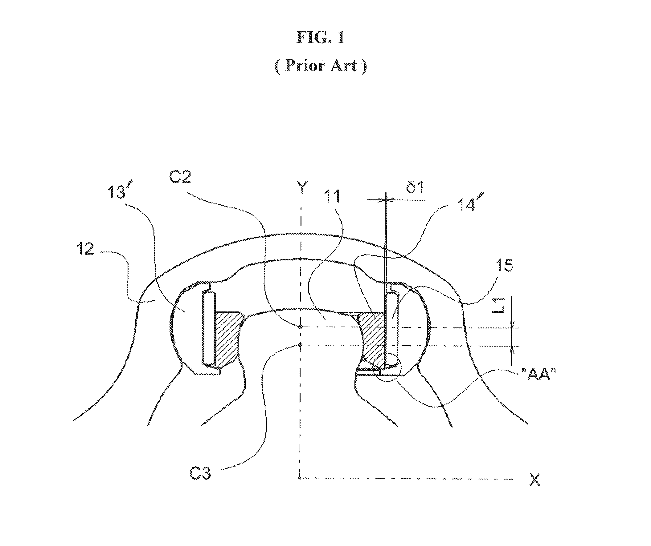
[0008]As will be described in details below, the constant velocity joint of the present invention provides a tapered roller structure in the inner and outer rollers thereof. Moreover, according to the present invention, the outer roller 13 is effectively prevented from self-separation from the roller assembly, although the outer roller 13 does not include the projecting portion “AA” as in the conventional joint described above. Furthermore, the inner roller of the constant velocity joint of the present invention provides an optimal configuration and dimension which can provide a sufficient durability and mechanical strength to the roller assembly, while also considering the assembling and disassembling performance of the constant velocity joint without undue difficulties.
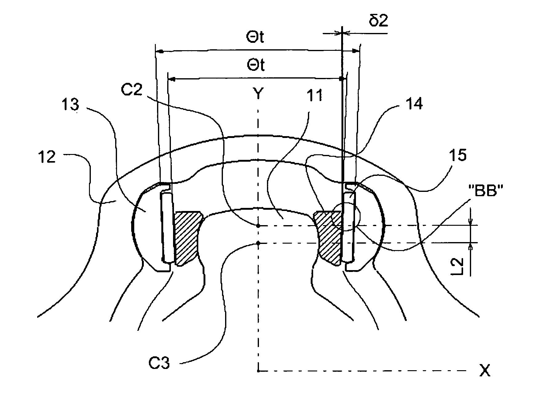
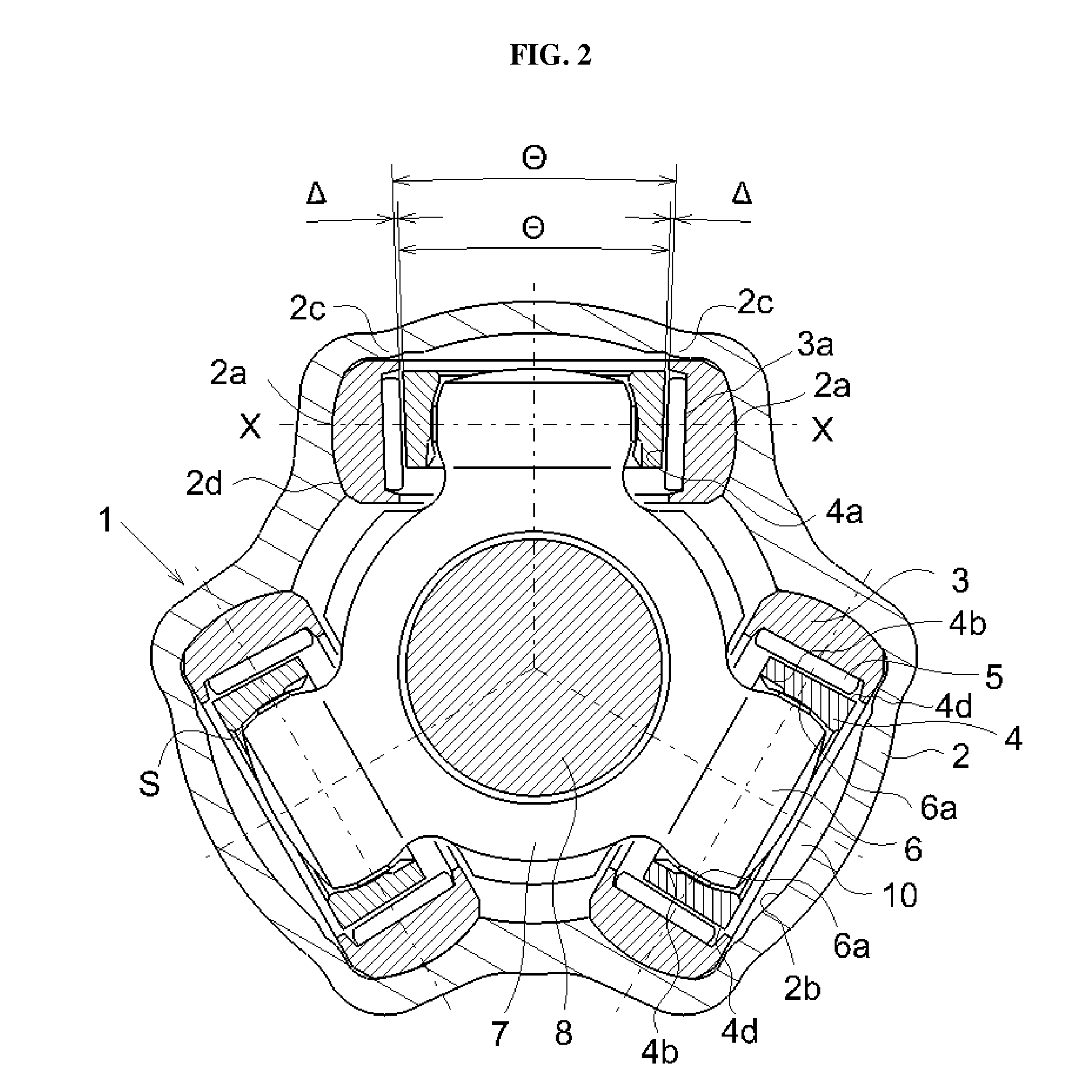
[0010]As illustrated in FIGS. 2 and 3 and is also specifically discussed in application Ser. No. 11 / 750,138, owing to the tapered structures of the roller kit, the transmitting torque is transferred through the contact made between the tapered outer face 4a of the inner roller 4 and needle rollers 5 and between the needle rollers 5 and the tapered inner face 3a of the outer roller 3. This causes the roller assembly 12 to be biased toward the inner portion 2d (i.e., toward the boss 11 of the trunnion 6) of the groove guides 10 of the housing 2, by an axial component Fv of a load which is acting in the direction of the axis of the trunnion and toward the boss of the trunnion. Accordingly, this tapered configuration facilitates the roller assembly 12 to rotate smoothly with slight bias toward the boss of the tripod while reducing the frictional contacts between the lateral (outer) side of the outer roller 3 and the lateral tracking guide 2c of the housing 2.
[0011]Due to the tapered structures in the roller assembly, the inward movement of the inner roller 4 (or outer roller 3) toward the boss of the trunnion 6 causes the clearance Δ between the outer roller 3 and inner roller 4 to be decreased gradually. As a result, the inward movement of the inner roller 4 (or outer roller 3) is limited to a predetermined amount by the contact or jamming of the inner roller 4 against the needle rollers 5 and outer roller 3 due to the tapered structure of the roller assembly. Accordingly, this tapered roller configuration helps the inner roller 4 or outer roller 3 to limit its axial movement within a permissible range, thus preventing the roller from separating or self-disassembling from the roller assembly.
[0012]As such, the present applicant has discovered that the provision of tapered roller structures in the constant velocity joint produces substantial advantages and benefits, for example, such as reduction of adverse frictional contacts and prevention of self separation of the roller assembly as discussed above.
[0014]The present applicant has also discovered that selection of an optimal configuration and optimal size of the inner roller is also very significant to provide a required mechanical strength, while also contemplating the assembling and disassembling performance of the joint. In order for the tapered roller structure of the invention to provide the same or enhanced durability or strength as with the conventional tripod joint with straight rollers, while also enabling the assembling and disassembling process of the roller assembly with the spider trunnion to be performed without difficulties, the inner roller is configured to have an optimal length LL (the distance from the center C3 of the spider trunnion to the lower edge P of the inner concave contact surface of the inner roller) which can cover the entire elliptical contact area of the roller assembly that is displaced inwardly due to the tapered roller structure. As will be disclosed below in details, the length LL per the taper angle and the spider trunnion radius will be defined, preferably based on the range of taper angle, the range of typical spider trunnion radius, PCD of spider, and the acceptable overlap in the rollers for suitably assembling and disassembling the rollers.

