
Apparatus and method for computing location of a moving beacon using time difference of arrival and multi-frequencies

a technology of radio beacon and computing apparatus, which is applied in the field of radio beacon location computing apparatus and method, can solve the problems that the accurate location of the radio beacon b>100/b> cannot be detected in an area, and the conventional method cannot be applied in an environment where the coverage is low, so as to remove phase ambiguity

Inactive Publication Date: 2011-09-27
ELECTRONICS & TELECOMM RES INST
View PDF13 Cites 34 Cited by
  • Summary
  • Abstract
  • Description
  • Claims
  • Application Information

AI Technical Summary

Benefits of technology

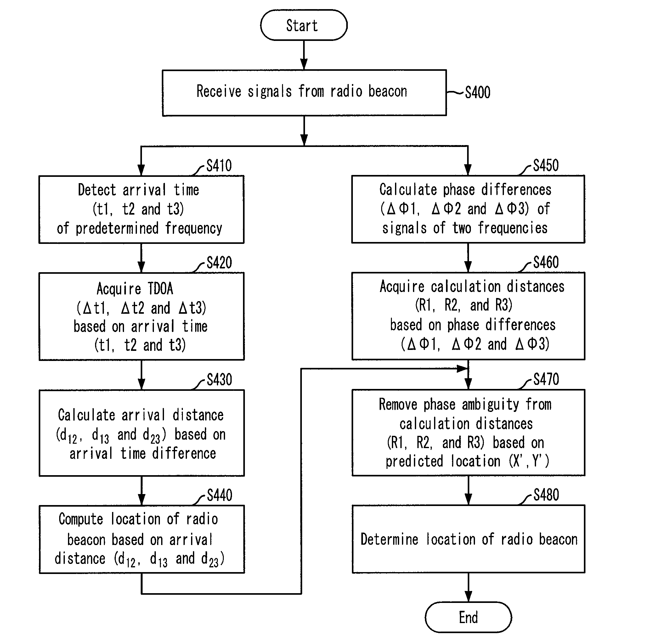
The present invention provides a method and system for accurately computing the location of a radio beacon by using time difference of arrival and multiple frequencies, and removing phase ambiguity from the calculation distances. This allows for a more accurate location tracking in an environment where the radio beacon is not within the coverage of a single base station. The technical effect of this invention is to enable the accurate location tracking of a radio beacon without limitation in distance.

Problems solved by technology

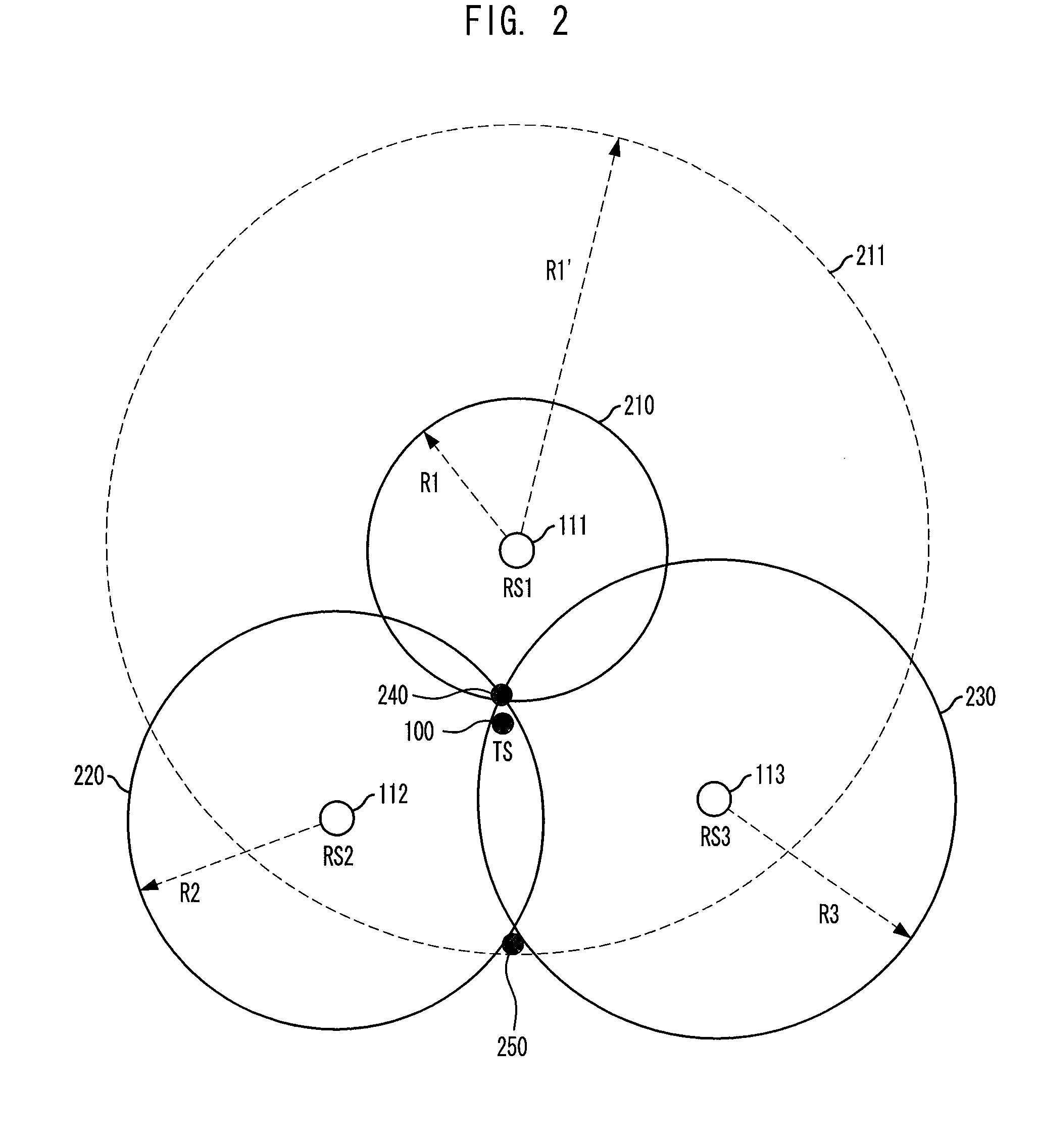
Generally, the method that a radio beacon transmits signals in two or more frequencies and base stations receive the radio signals and compute a distance by calculating a phase difference based on a frequency interference phenomenon has a problem that the calculation for acquiring a distance between a base station and a radio beacon produces a plurality of solutions where the phase differences between the two frequencies are ΔΦ, 2π+ΔΦ, 4π+ΔΦ, .
Thus, the conventional method cannot be applied to an environment where the coverage is larger than the phase difference of the two frequencies, i.e., 2π.
Therefore, there is a problem that the accurate location of the radio beacon 100 cannot be detected in an area where the phase difference between the two frequencies is larger than 2π.

Method used


Image

  • Apparatus and method for computing location of a moving beacon using time difference of arrival and multi-frequencies
  • Apparatus and method for computing location of a moving beacon using time difference of arrival and multi-frequencies
  • Apparatus and method for computing location of a moving beacon using time difference of arrival and multi-frequencies

Examples


Embodiment Construction

[0024]Other objects and aspects of the invention will become apparent from the following description of the embodiments with reference to the accompanying drawings, which is set forth hereinafter. Also, when it is considered that detailed description on a related art to which the present invention pertains may obscure the points of the present invention, the description will not be provided herein. Hereinafter, specific embodiments of the present invention will be described with reference to the accompanying drawings.

[0025]FIG. 3 is an exemplary block view illustrating a radio beacon location computing system using Time Difference Of Arrival (TDOA) and multiple frequencies in accordance with an embodiment of the present invention.

[0026]Referring to FIG. 3, the radio beacon location computing system includes a radio beacon (TS) 310, a plurality of base stations RS1, RS2 and RS3320, and a location computing server 330.

[0027]The radio beacon310 transmits signals in two frequencies f1 a...


PUM


Abstract

Provided is an apparatus and method for computing the location of a radio beacon by using Time Difference Of Arrival (TDOA) and multiple frequencies. The apparatus and method of the present invention compute the location of a radio beacon without limitation in distance by using multiple frequencies and time difference of arrival to resolve the problem of phase ambiguity. A radio beacon location computing system includes a plurality of base stations configured to receive signals of multiple frequencies transmitted from the radio beacon, and detect and output phase differences and arrival time; and a location computing server configured to receive the phase differences and the arrival time outputted from the respective base stations, acquire calculation distances based on the phase differences, remove phase ambiguity from the calculation distances based on the arrival time, and compute the location of the radio beacon.

Description

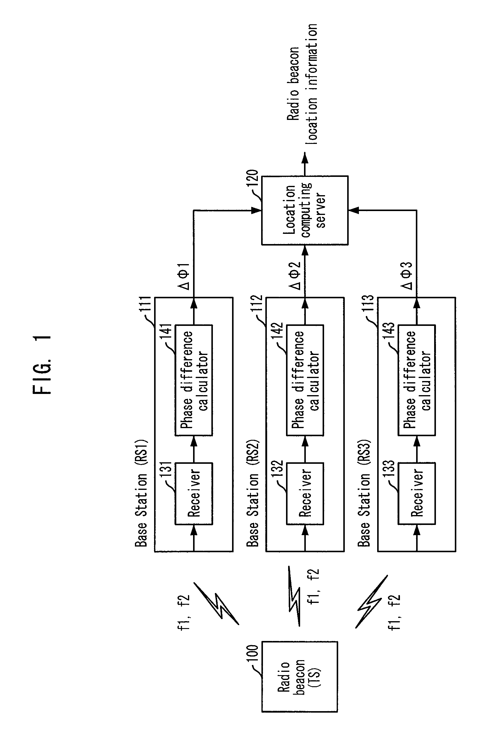
TECHNICAL FIELD[0001]The present invention relates to a radio beacon location computing apparatus and method for determining the location of a radio beacon; and, more particularly, to a radio beacon location computing apparatus that can determine the location of a radio beacon by receiving signals transmitted from the radio beacon at a plurality of base stations and using Time Difference Of Arrival (TDOA) information and phase difference information of the received signals, and a method thereof.BACKGROUND ART[0002]A general method of tracing the location of a radio beacon will be described hereinafter with reference to the accompanying drawings.[0003]FIG. 1 is an exemplary view showing a typical radio beacon location computing system.[0004]Referring to FIG. 1, a radio beacon 100 transmits signals in two or more frequencies f1 and f2, which are independent from each other. Then, at least three base stations 111, 112 and 113 receive the signals in the two frequencies, extract phase di...

Claims


Application Information

Patent Timeline
Patent Type & Authority Patents(United States)
IPC IPC(8): G01S1/24G01S5/14H04W64/00
CPCG01S5/06G01S5/14H04W64/00H04W24/00H04W88/10
Inventor SEONG, NAK-SEONLIM, CHOON-SIKPYO, CHEOL-SIGCHAE, JONG-SUK
Owner ELECTRONICS & TELECOMM RES INST
Learn More