Arrangement For Shaping Laser Radiation

a laser radiation and arrangement technology, applied in the direction of optics, instruments, optical elements, etc., can solve the problems of insufficient brightness, often insufficient achievable brightness, and often insufficient arrangement efficiency, so as to reduce the divergence of sub-beams

Inactive Publication Date: 2014-02-20
LIMO PATENTVERWALTUNG GMBH & CO KG
View PDF2 Cites 5 Cited by
  • Summary
  • Abstract
  • Description
  • Claims
  • Application Information

AI Technical Summary

Benefits of technology

[0020]Furthermore, slow axis collimating means may be arranged behind the second substrate in the beam propagat

Problems solved by technology

As a result, dark areas exist between the sub-beams originating from the individual emitters, which have an adverse effect on the so-called “brightness” (specific intensity) of the laser radiation.
It has been observed that such an arrangement often does not provide adequate efficiency, since a large part of the optical

Method used


Image

  • Arrangement For Shaping Laser Radiation
  • Arrangement For Shaping Laser Radiation
  • Arrangement For Shaping Laser Radiation

Examples


Embodiment Construction

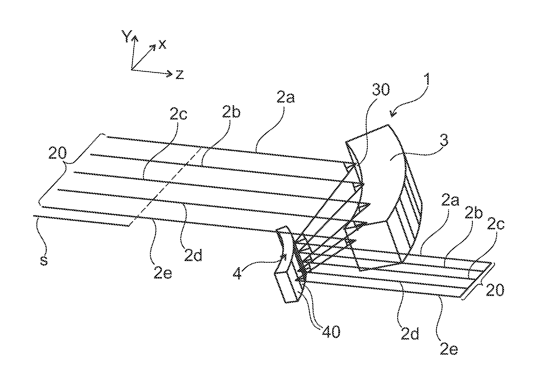
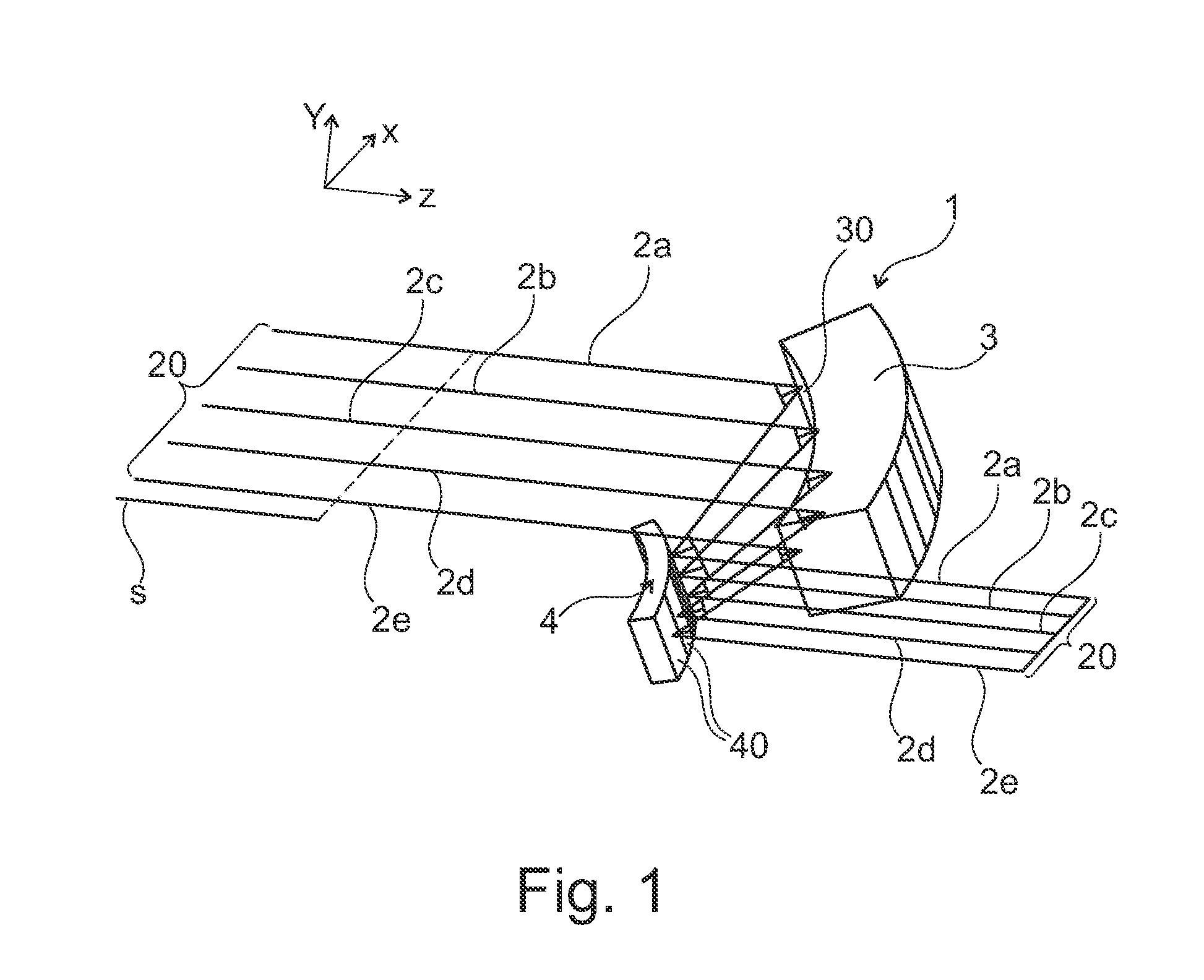
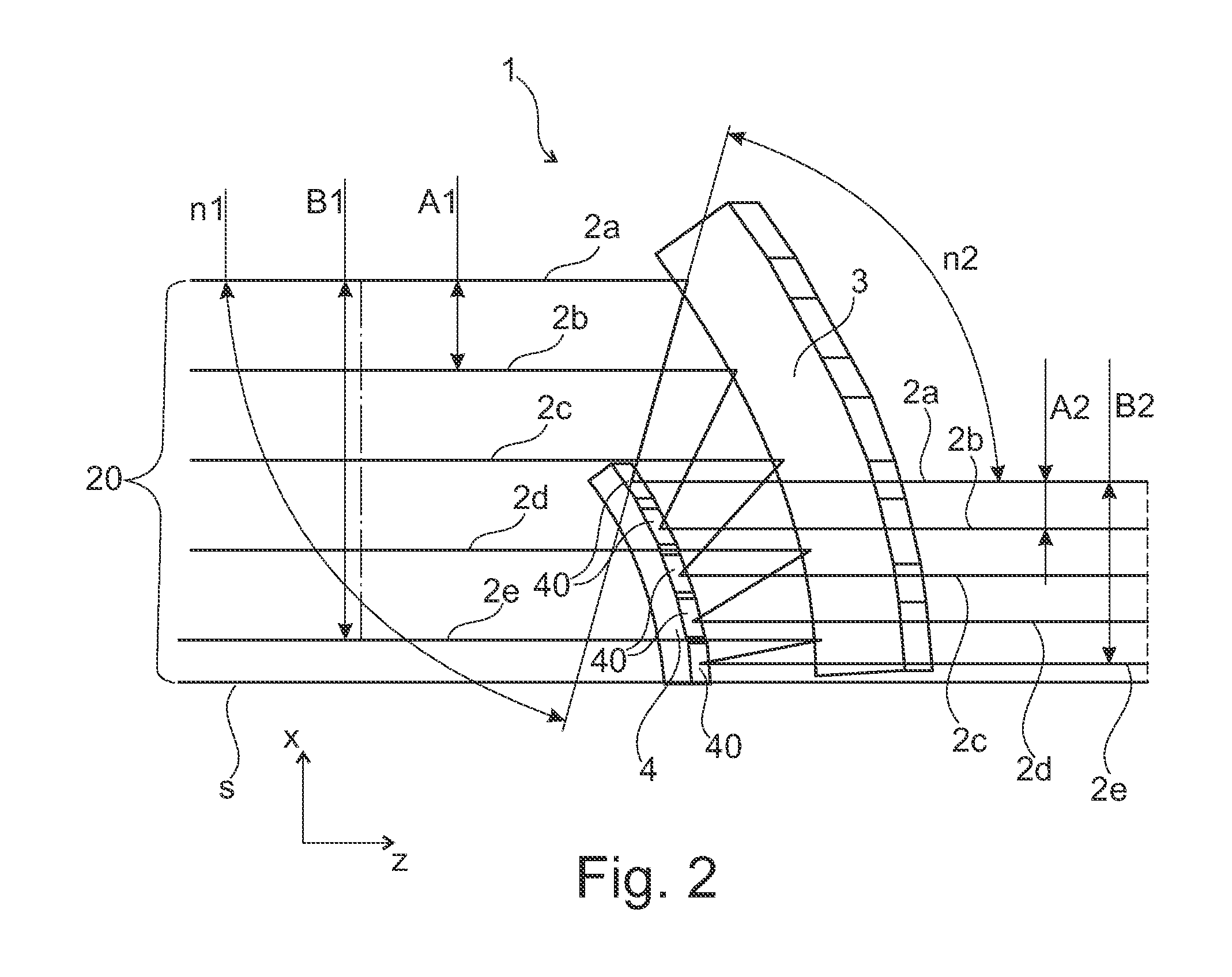
[0025]To simplify the following description, Cartesian coordinate systems, which define the mutually orthogonal x-, y- and z-directions, are shown in all Figures.

[0026]In FIGS. 1-3, reference numeral 2a-2e indicate several (five exemplary) sub-beams that can be emitted from particular emitters of a laser diode bar (not explicitly shown here for sake of simplicity) and form a laser beam (laser radiation) 20. The propagation direction, in which the sub-beams 2a-2e propagate, is here the z-direction. The individual emitters of such laser diode bar are spaced from one another in the so-called slow axis (in this case in the x-direction). Typically, each emitter of such a laser diode bar may have a length of about 150 μm in the slow axis, wherein the spacing between two adjacent emitters in this direction is approximately 400 μm. The individual emitters thus emit sub-beams 2a-2e of the laser radiation of the laser diode bar.

[0027]The arrangement shown in FIG. 1 may include a fast-axis col...


PUM


Abstract

An arrangement for shaping laser radiation with mutually spaced-apart parallel sub-beams in a first direction perpendicular to a propagation direction of laser radiation, including a first substrate with several reflective surfaces on which the sub-beams reflects, and a second substrate with several reflective surfaces and being offset relative to the first substrate, so that the sub-beams reflected by the reflective surfaces of the first substrate reflects by the reflective surfaces of the second substrate, wherein the reflective surfaces of the first substrate and the reflective surfaces of the second substrate are arranged and configured such that the sub-beams of the laser radiation to be shaped can be reflected in such a way that they have after the reflection on the reflective surfaces of the second substrate in the first direction a smaller spacing from one another than before the reflection on the reflective surfaces of the first substrate.

Description

[0001]This application claims priority to DE 10 2012 107 456.9 filed on Aug. 14, 2012.BACKGROUND OF THE INVENTION[0002]The present invention relates to an arrangement for shaping laser radiation.[0003]Definition:[0004]The terms light or illumination or laser radiation are not intended to be limited to the visible spectral wavelength range. Rather, the term light or illumination or laser radiation is used in the context of this application for electromagnetic radiation in the entire wavelength range from FIR to XUV. In the propagation direction of the light, the mean propagation direction of light indicates, particularly when this is not a plane wave, or is at least partially convergent or divergent. Light beam, sub-beam, or ray refers, unless expressly stated otherwise, not to an idealized beam of the geometrical optics, but to a real light beam such as a laser beam having a Gaussian profile, which does not have an infinitesimally small beam cross-section, but rather an extended bea...

Claims


Application Information

Patent Timeline
IPC IPC(8): G02B27/09
CPCG02B27/0983
Inventor STOEHR, DETLEF
Owner LIMO PATENTVERWALTUNG GMBH & CO KG
Why Eureka
Try Eureka