
Image-capturing unit and image-capturing apparatus

a technology of image-capturing unit and image-capturing apparatus, which is applied in the field of image-capturing units, can solve the problems of reducing reducing the accuracy of optical members, so as to reduce the adverse effect of heat and increase the position accuracy of optical members

Inactive Publication Date: 2011-09-27
NISCA KK
View PDF5 Cites 2 Cited by
  • Summary
  • Abstract
  • Description
  • Claims
  • Application Information

AI Technical Summary

Benefits of technology

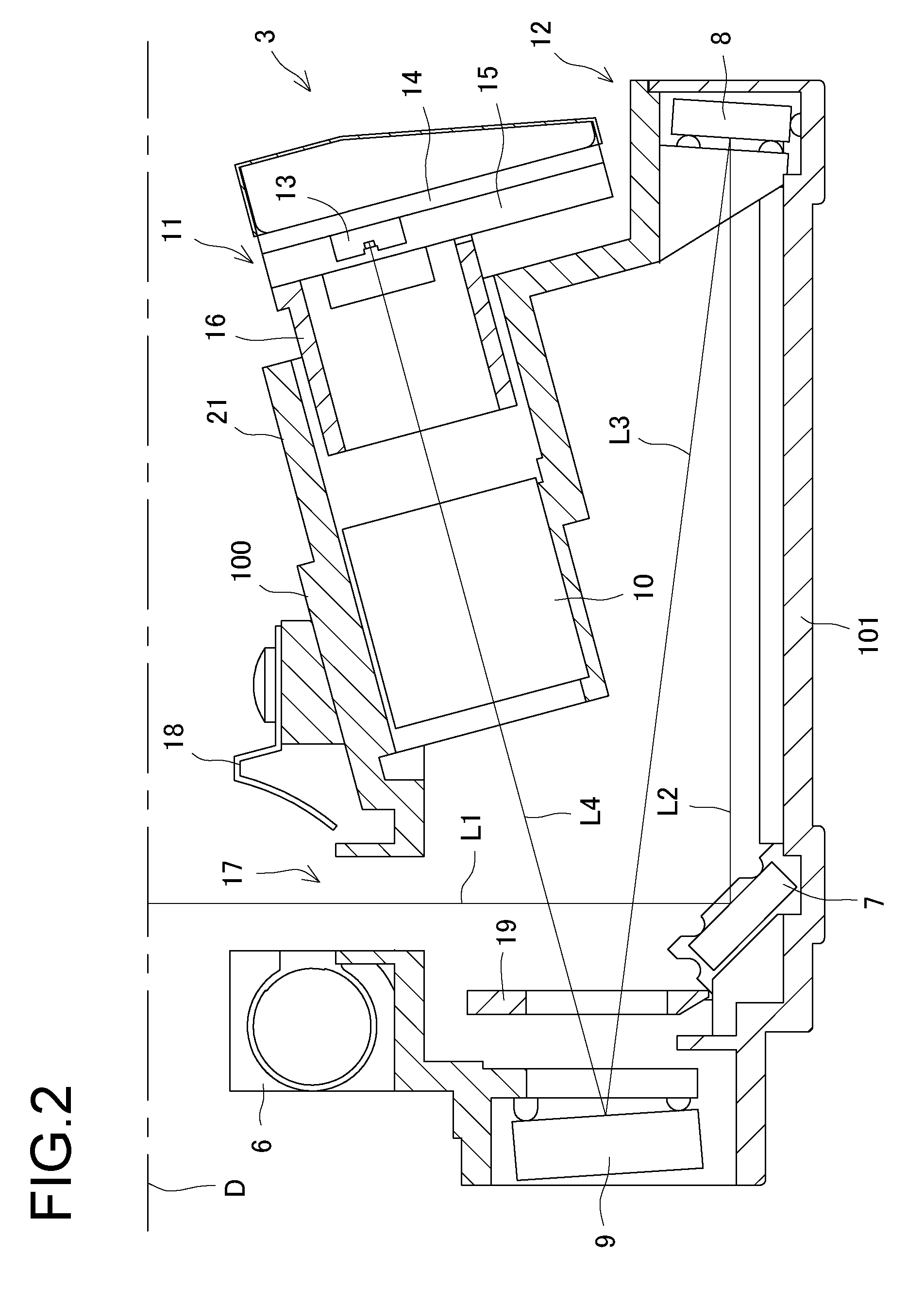
This design effectively blocks radiation heat from the light source, improves the accuracy of the mirror group's positioning, and simplifies the mold shape, reducing assembly costs and increasing the accuracy of the mirror support section.

Problems solved by technology

However, the light sources, such as xenon lamps, often used for scanners generate an increased quantity of heat when providing an increased quantity of light.
A consequent problem that arises is that heat from the light source deleteriously deforms the mirrors and other optical components.
This complicates the shape of the mold.
This further complicates the shape of the mold.
In particular, the level of complexity of the shape of the mold increases with decreasing distance to the bottom the frame; that is, the level of complexity increases consistently with the distance from the opening in the unit.
This reduces molding accuracy.
However, this may increase the number of parts required and the number of assembly steps, sharply increasing costs.

Method used


Image

  • Image-capturing unit and image-capturing apparatus
  • Image-capturing unit and image-capturing apparatus
  • Image-capturing unit and image-capturing apparatus

Examples


Embodiment Construction

[0016]An embodiment of the present invention will be described below with reference to the drawings.

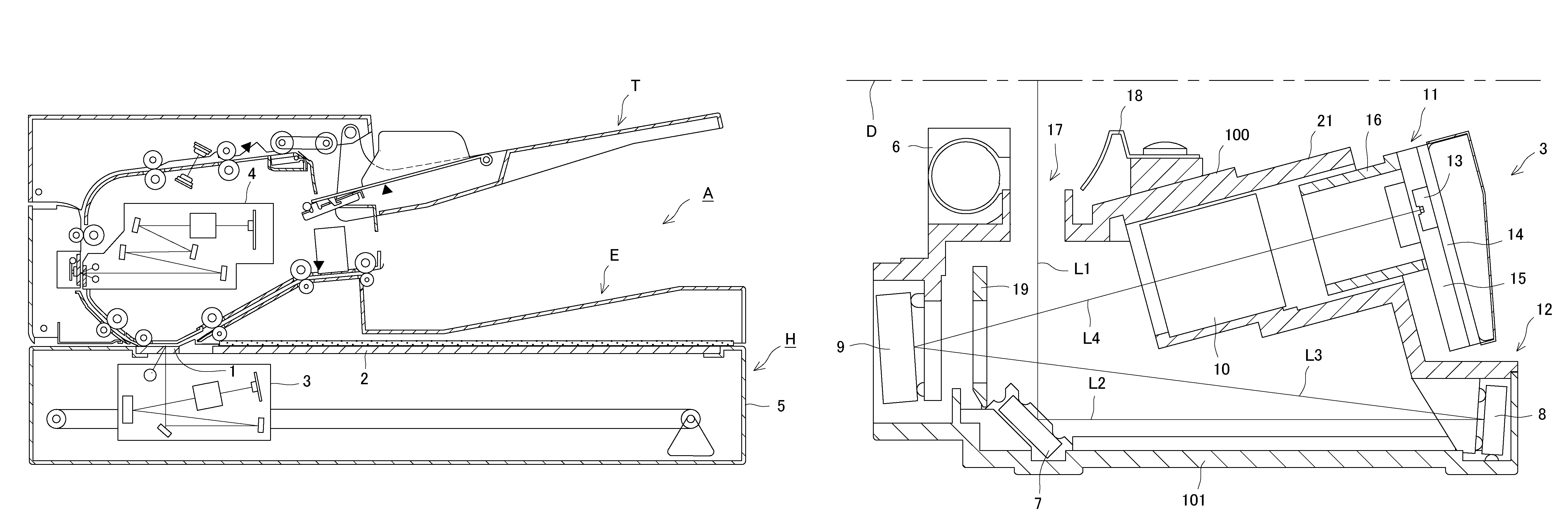
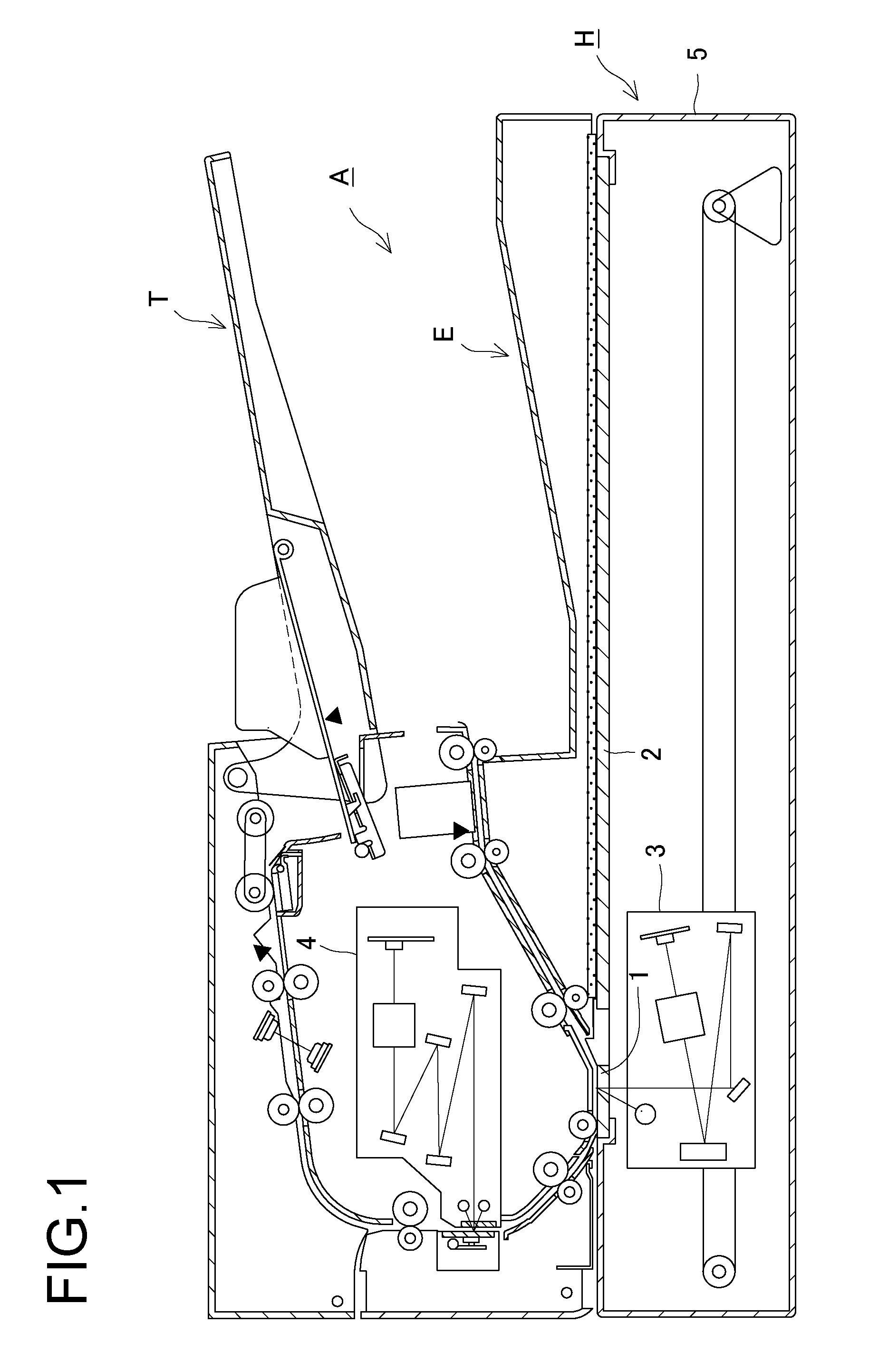
[0017]FIG. 1 is a sectional view showing an image-capturing apparatus comprising a document conveying device according to an embodiment of the present invention. The image-capturing apparatus to which the present invention is applied will be described with reference to FIG. 1. The image-capturing apparatus H can be independently used as a scanner or connected to an image forming apparatus main body such as a printer so as to serve as a part of an MFP (Multi Function Peripheral). Reference numeral A in the figures denotes a document conveying device mounted in the image-capturing apparatus H. The document conveying device A separates a document from a set of documents on a sheet feeding tray T, conveys the sheet over a top surface of first contact glass 1 in the image-capturing apparatus H, and discharge the sheet onto a sheet discharging tray E. The document conveying device A compris...


PUM


Abstract

For an image-capturing unit having a light source and mirrors directing light reflected from a scanned document into a lens condensing the light onto a photoelectrically converting image sensor, a synthetic resin housing. The housing is composed of an open-ended upper frame having a top plate from which sidewalls extend, encompassing an internal space. A mounting surface for anchoring the light-source is formed on the upper side of the upper-frame top plate, and formed on the lower side of the upper-frame top plate is a pedestal on which the lens is supported. Mirror-support projections are formed on the lower side of the upper-frame top plate, or on the upper-frame sidewalls, to support the mirrors from below the lens. With this housing, the influence of heat from the light source on the optics is minimized, improving the mirrors' positional accuracy.

Description

BACKGROUND OF THE INVENTION[0001]1. Technical Field[0002]The present invention relates to image-capturing units that capture image information from documents, and to image-capturing apparatus furnished with such image-capturing units.[0003]2. Description of the Related Art[0004]Recent years have seen demands for the speed at which scanners capture information to be made faster. To make the capturing speed faster while acquiring satisfactory images requires a light source with an increased quantity of light.[0005]However, the light sources, such as xenon lamps, often used for scanners generate an increased quantity of heat when providing an increased quantity of light. A consequent problem that arises is that heat from the light source deleteriously deforms the mirrors and other optical components.[0006]Furthermore, a unit frame on which the optical members are supported has been composed of a synthetic resin in order to reduce the weight of the unit frame. The unit frame has thus be...

Claims


Application Information

Patent Timeline
Patent Type & Authority Patents(United States)
IPC IPC(8): H04N1/04
CPCG03B27/70
Inventor SHIMIZU, MASAONODA, MAMORU
Owner NISCA KK
Learn More