Methods for using a detector to monitor and detect channel occupancy

a detector and channel technology, applied in the field of monitoring channels, can solve problems such as network offline, inability to solve, and other forms of potential interference, and achieve the effects of avoiding interference, avoiding interference, and avoiding interferen

Inactive Publication Date: 2011-09-27
SHARED SPECTRUM
View PDF209 Cites 99 Cited by
  • Summary
  • Abstract
  • Description
  • Claims
  • Application Information

AI Technical Summary

Benefits of technology

[0009]If a non-cooperative transmission is detected in the primary channel by any participating network station, the network initiates the migration to the backup channel to avoid interference with a detected non-cooperative source. Prior to switching channels, each network station verifies the availability of the backup channel. Successful validation provides increased confidence that the migration to the backup channel will not cause interference.
[0010]The proposed verification process involves asynchronous detection such that the spectrum measurement is not performed during the regular transmission gap intervals, or any other periodically scheduled time intervals, within the frame. The verification process is necessary to avoid the situation when the gaps used by the network stations to perform detection measurement are synchronized to the gaps of non-cooperative transmission source(s) operating over the intended backup channel. The situation is common when both channels are occupied by the same type of network. The present invention avoids interference due to the possibility of synchronized transmission gaps.

Problems solved by technology

Other forms of potential interference may arise after the network is established.
This solution, however, is not feasible as the channel may never become available and the network cannot be offline for any period of time.
Other networks may be using the frequency of the backup channel, and any migration to the frequency would cause problems.
Thus, the occupancy of both frequency channels impacts the sustainability of the network.

Method used


Image

  • Methods for using a detector to monitor and detect channel occupancy
  • Methods for using a detector to monitor and detect channel occupancy
  • Methods for using a detector to monitor and detect channel occupancy

Examples


Embodiment Construction

[0024]Reference will now be made in detail to the preferred embodiments of the present invention. Examples of the preferred embodiments are illustrated in the accompanying drawings.

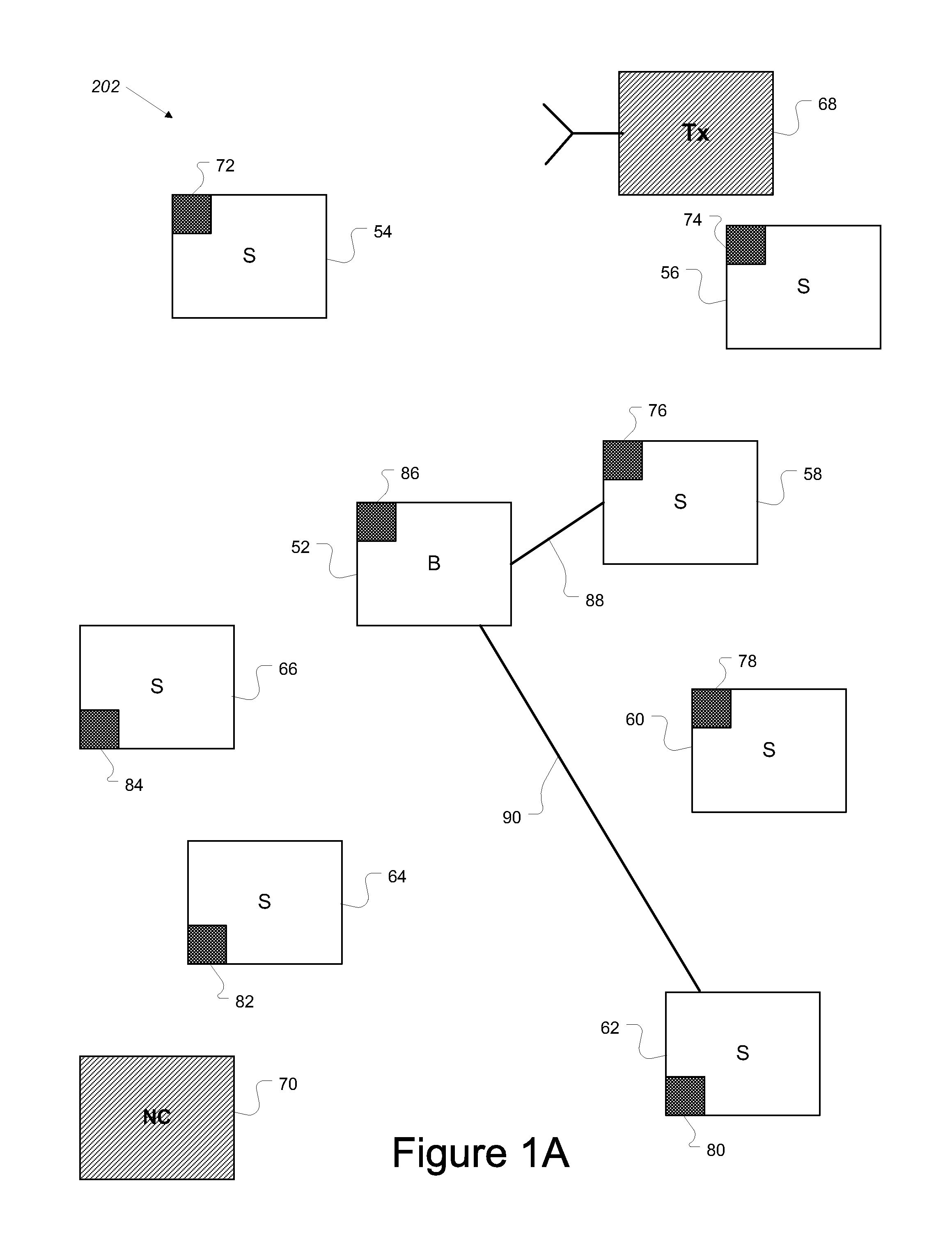
[0025]FIG. 1A depicts a network 202 including stations according to the disclosed embodiments. Network 202 allows communication and data exchange between the stations. Network 202 is not limited by geography, frequency spectrum or configuration. Network 202 must avoid interfering with other networks or transmitters and operates on a frequency not in use by other transmission sources. Once any interference is detected, network 202 switches from the present operating frequency to another.

[0026]Network 202 includes base station 52 and subscriber stations 54, 56, 58, 60, 62, 64 and 66. The number of stations within network 202 is shown for illustrative purposes only. The number of stations within network 202 is not limited to the amount shown in FIG. 1, and may include any number of stations. Further, network...


PUM


Abstract

Methods for using a detector to monitor and detect channel occupancy are disclosed. The detector resides on a station within a network using a framed format having a periodic time structure. When non-cooperative transmissions are detected by the network, the detector assesses the availability of a backup channel enabling migration of the network. The backup channel serves to allow the network to migrate transparently when the current channel becomes unavailable. The backup channel, however, could be occupied by another network that results in the migrating network interfering with the network already using the backup channel. Thus, the detector detects active transmission sources on the backup channel to determine whether the backup channel is occupied. Methods for using the detector include scheduling detection intervals asynchronously. The asynchronous detection uses offsets from a reference point within a frame.

Description

[0001]This invention was made with Government support under Contract FA8750-05-C-0150 awarded by the Air Force. The Government has certain rights in this invention.FIELD OF THE INVENTION[0002]The present invention relates to monitoring channels to avoid interference with other wireless devices operating over the same channels. More particularly, the present invention relates to different methods to detect occupancy of the channel designated as a backup channel for wireless transmission sources prior to migration of the sources to the backup channel when the current channel is unavailable.DESCRIPTION OF THE RELATED ART[0003]Wireless networks enable connectivity between different stations, nodes and the like. The different stations may reside in different locations and operate on frequency channel(s) designated for the network. The number of channel allocations available depends on the total amount of designated spectrum as well as spectrum occupancy.[0004]Some networks are allowed to...

Claims


Application Information

Patent Timeline
Patent Type & Authority Patents(United States)
IPC IPC(8): H04J1/16H04L12/26H04W16/14
CPCH04W16/14H04W56/002H04W56/00H04W56/003H04B7/022H04W72/0446H04W74/0816H04B17/14H04B17/318H04B7/0647
Inventor MCHENRY, MARK A.DAIN, DMITRYLIVSICS, JEVGENIJSSTEADMAN, KARLRITTERBUSH, OLGA
Owner SHARED SPECTRUM
Why Eureka
Try Eureka