Hinged attachment of headgear to a helmet

a technology for ear accessories and helmets, applied in protective garments, instruments, optical elements, etc., can solve the problems of wearers experiencing discomfort, improper fit and/or less protection, and earphones adding weight and not functioning, etc., to facilitate the insertion of ear accessories

Active Publication Date: 2011-10-04
GENTEX CORP
View PDF39 Cites 37 Cited by
  • Summary
  • Abstract
  • Description
  • Claims
  • Application Information

AI Technical Summary

Benefits of technology

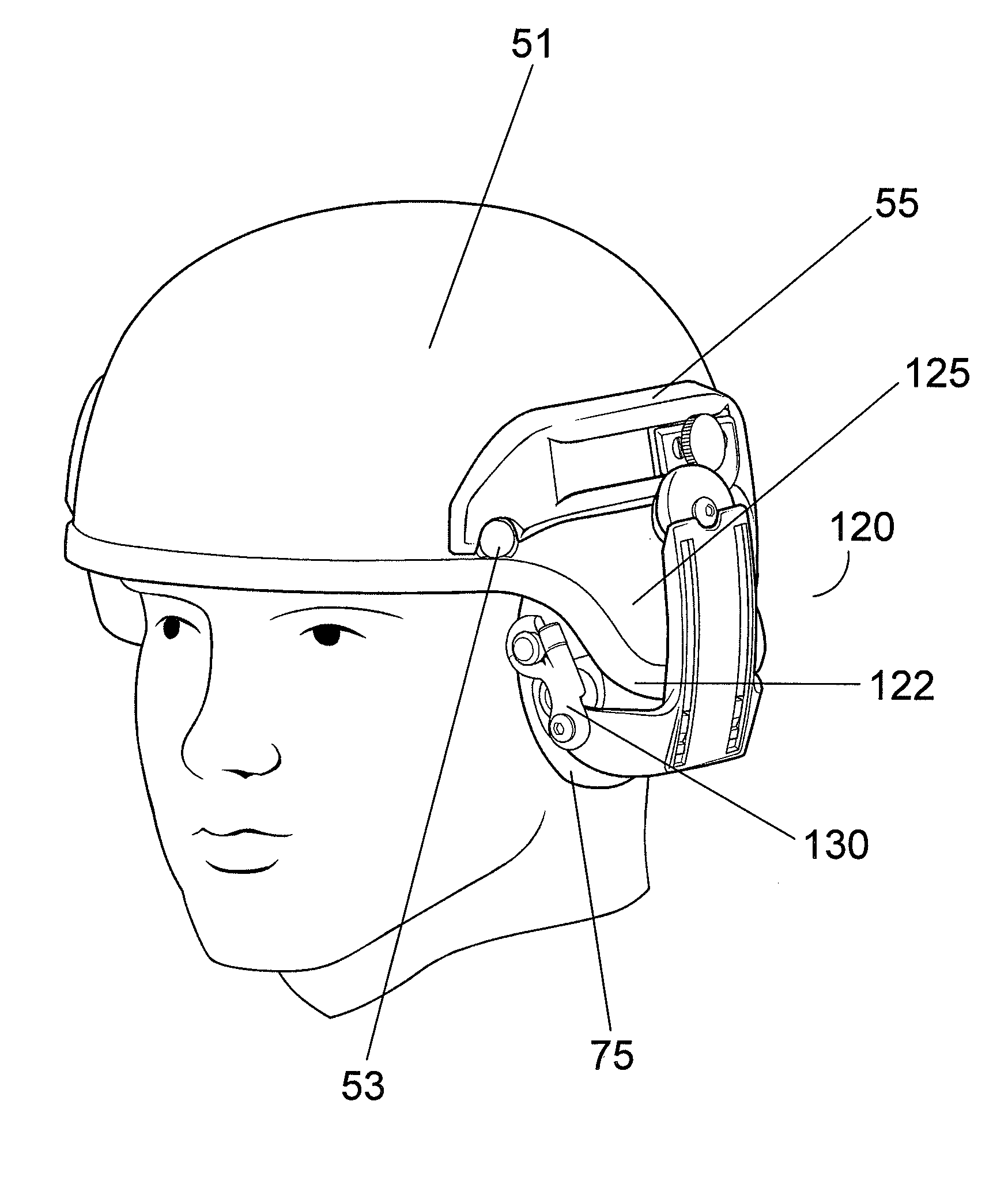
[0008]The overall length of the pivot arm is selected to facilitate positioning and removal of the ear accessory around the edge of the helmet shell. The length from center of the pivot point where the pivot arm joins the connecting member and the center of the split ring may be, for example, between 0.5 inch and 2 inches (e.g., 1.25 inches). The pivot arm may include features that facilitate adjustment of the pressure placed by the ear accessory on the wearer's ear.
[0009]In some embodiments, a connecting member is pivotably connected to the pivot arm and slidably joined to a shoulder member, thereby forming an attachment assembly. The pivot arm and connecting member joined together may also be optionally attached to a conventional headband (instead of joining the shoulder member) to support the ear accessory without the helmet. The slidable connection between the connecting member and shoulder member provides adjustment of the ear accessory in height to obtain a comfortable position over the wearer's ear.
[0010]A shoulder member may support connection of the hinge mechanism to the helmet, for example, using the slidable mounting rail described below (it being understood that alternative means for attaching the shoulder member to the helmet may be substituted without detracting from the benefits of the present invention). The shoulder member of the hinge mechanism may also provide rotation to allow the ear accessory to rotate to the back of the helmet, facilitating stowage when the accessory is not needed.
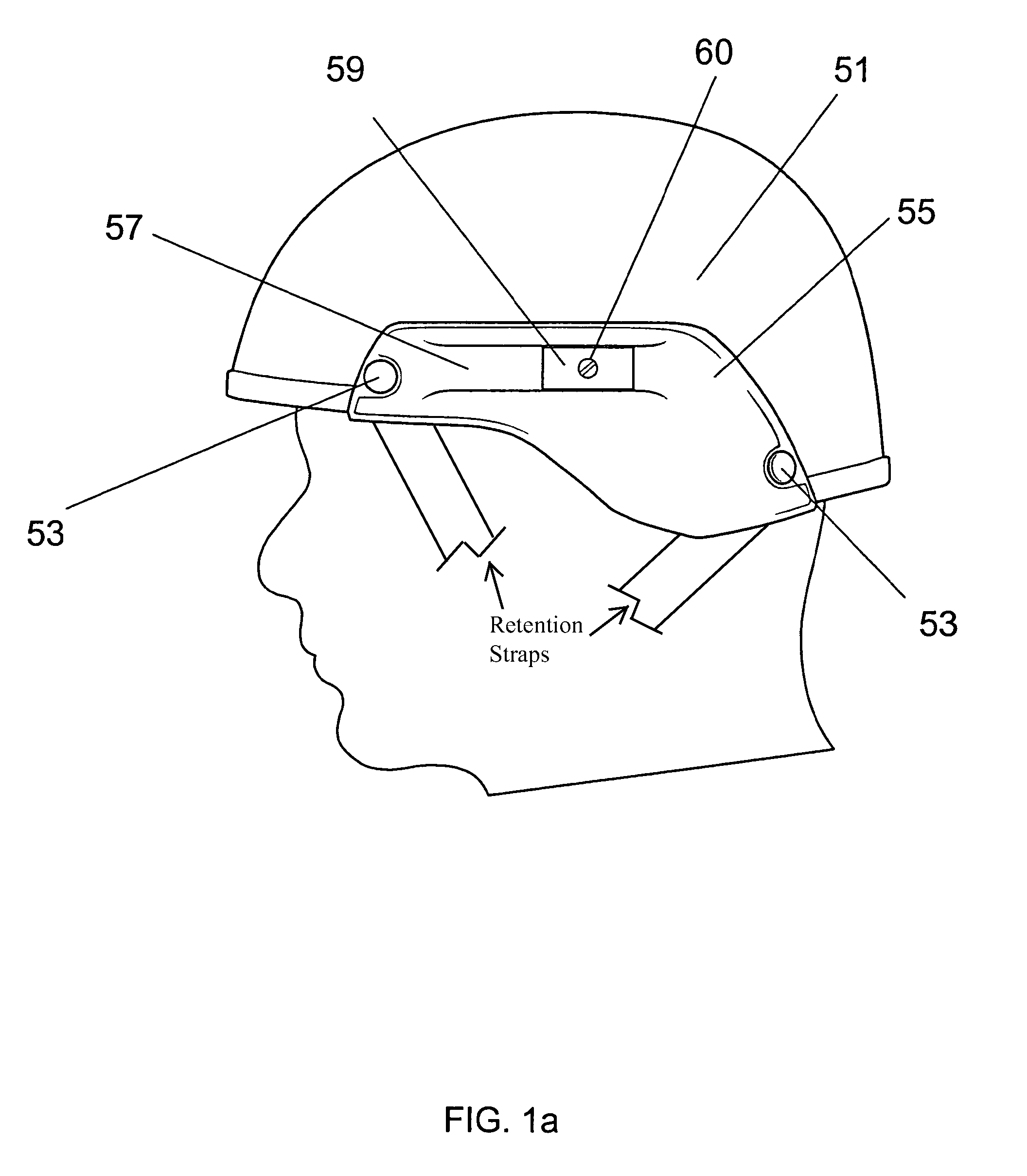
[0011]A preferred mounting platform (herein referred to as a “mounting rail”) accepts the ear-accessory hinge mechanism and, if desired, additional accessories at desired locations and with positional security. The mounting rail may have slides, threaded holes, or other mounting fixtures suited to securing the accessories. The mounting rail may be configured to present a relatively low-profile protrusion from the helmet using physical surfaces that offer low risk of snagging or being caught in external devices when accessories are not in place. The mounting rail allows for adjustment of the position of the accessories when they are attached to the rail, which desirably accepts more than one optional accessory.
[0015]Accordingly, in a first aspect, the invention relates to a mounting facility for a safety helmet of the type having a bulge or protrusion on a side thereof to form a cavity therein, where the cavity extends to a terminal edge of the helmet and overlies a wearer's ear. The mounting facility comprises a fixture configured for attachment to the helmet above the bulge and, attached to the fixture, an articulating arm assembly for receiving an ear accessory. The arm assembly facilitates insertion of the ear accessory into the cavity and its removal there from around the terminal edge.
[0018]In a third aspect, the invention relates to a safety helmet comprising a bulge or protrusion on a side thereof to form a cavity therein, the cavity extending to a terminal edge of the helmet and overlying a wearer's ear, a fixture attached to the helmet above the bulge and, attached to the fixture, an articulating arm assembly for receiving an ear accessory. The arm assembly facilitates insertion of the ear accessory into the cavity and its removal there from over the terminal edge. The helmet may include other features as described above.

Problems solved by technology

Unfortunately, because the earphones add weight and do not function in dismounted operations, and cannot be removed, the vehicle crew members are issued two helmets—the CVC helmet and a standard infantry helmet.
In some cases this repositioning results in improper fit and / or less protection in the case of impact.
Wearers may also experience discomfort due to the extra layer of retention elements separately holding the earphones and the helmet.

Method used


Image

  • Hinged attachment of headgear to a helmet
  • Hinged attachment of headgear to a helmet
  • Hinged attachment of headgear to a helmet

Examples


Embodiment Construction

[0042]For ease of presentation, the present discussion focuses first on a suitable mounting rail to which a hinged ear-accessory retention system may be mounted; preferred embodiments of the ear-accessory retention system itself are then described.

[0043]Mounting Rail

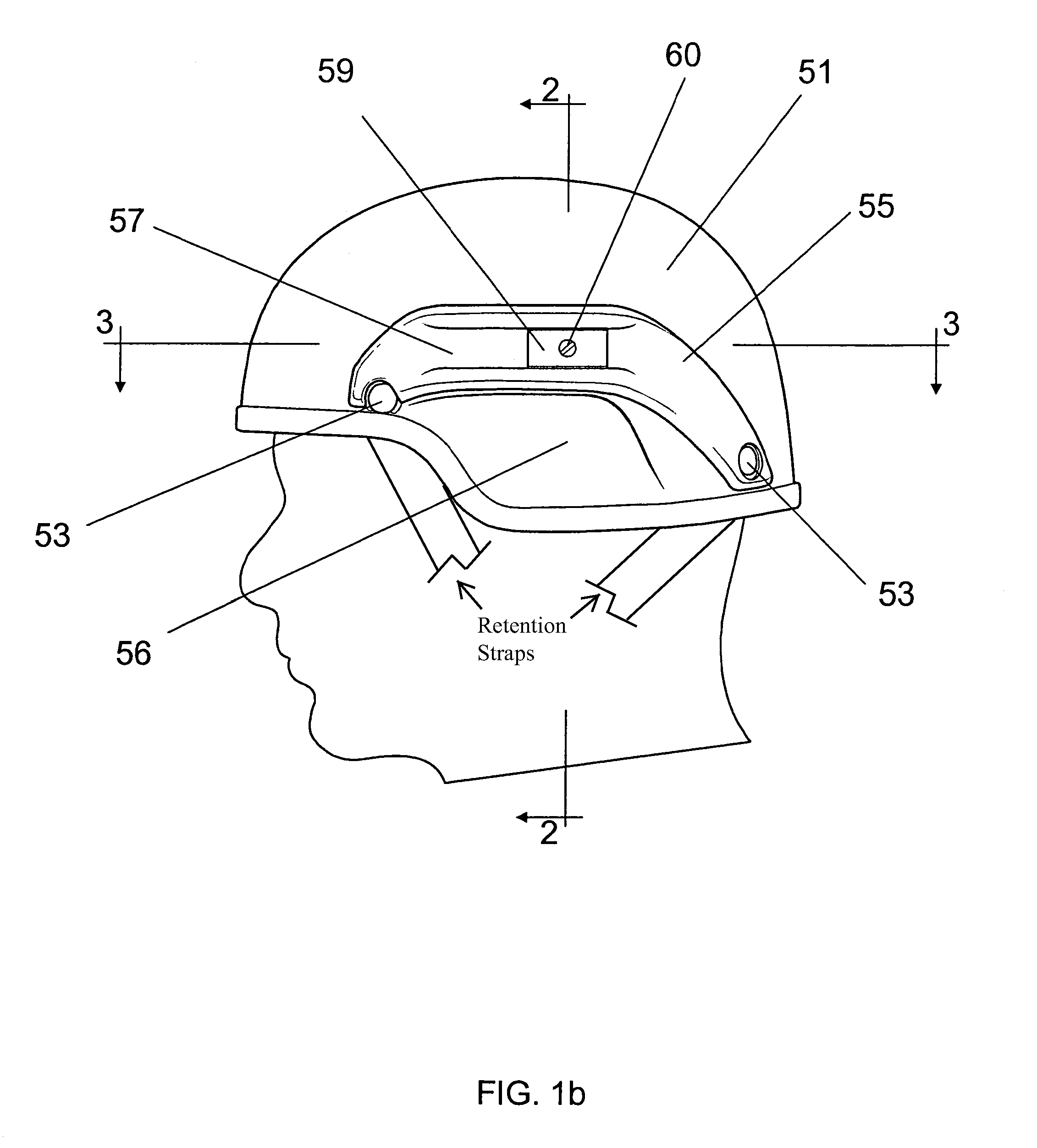
[0044]With reference to FIG. 1a, a helmet shell 51 is shown from the left side of the user's head (the right side having symmetrical features). A mounting rail 55 is included within a fixture preferably fabricated from nylon, polypropylene, or other synthetic plastic using injection molding processes, the bottom edge of which conforms to the bottom edge of the helmet shell 51. The fixture is secured to the exterior of helmet shell 51 by means of fasteners 53 in the front and back. In another embodiment, illustrated in FIG. 1b, mounting rail 55 is included within a fixture having a bottom edge that conforms to a convex extension 56 of helmet shell 51.

[0045]A recessed groove 57 in the mounting rail 55 slidably accepts a co...


PUM


Abstract

A hinge mechanism for attaching ear accessories to a helmet allows an accessory to be attached at a point outside the helmet shell utilizing, for example, a slidable mounting rail, and to reach under the edge of the helmet shell so that the accessory is supported in contact with the wearer's head. The hinge mechanism is well suited for use in connection with military helmets that have a “bulge” or protrusion over the ear.

Description

RELATED APPLICATIONS[0001]The present application is a continuation-in-part of U.S. Ser. No. 11 / 350,591, filed on Feb. 9, 2006, which claims priority to, and the benefits of, U.S. Ser. No. 60 / 691,307, filed Jun. 17, 2005; the present application also claims priority to U.S. Ser. No. 60 / 811,896, filed on Jun. 8, 2006. The entire disclosures of these applications are hereby incorporated by reference.FIELD OF THE INVENTION[0002]This invention relates to safety helmets, and in particular to attachment of accessories that may be optionally mounted onto the helmet.BACKGROUND OF THE INVENTION[0003]Helmets for head protection are worn in a variety of environments and for various purposes. Accessories may be added to the helmet according to the needs of the wearer and the demands of the use environment. Such accessories may, for example, provide additional protection, as in the case of a face shield; additional capability such as night vision; or communication in the case of earpieces.[0004]...

Claims


Application Information

Patent Timeline
Patent Type & Authority Patents(United States)
IPC IPC(8): A42B3/00
CPCA42B3/04A42B3/166A42B3/0406G02B23/12
Inventor ROGERS, DAVID C.ROGERS, CHARLES H.KEITH-LUCAS, DARWIN
Owner GENTEX CORP
Why Eureka
Try Eureka