Radiant heating/cooling tubing substrate with in plane bus

a technology of heating/cooling tubing and substrate, which is applied in the direction of heating types, lighting and heating apparatuses, laminated elements, etc., can solve the problems of time-consuming process, and inability to heat/cool tubing substrate in the plane,

Inactive Publication Date: 2011-10-04
FIEDRICH JOACHIM
View PDF24 Cites 21 Cited by
  • Summary
  • Abstract
  • Description
  • Claims
  • Application Information

AI Technical Summary

Problems solved by technology

Problems, however, can occur with in-plane routing between the radiant tubing loops and the control assemblies.
This is a time consuming process that is typically performed on-site using a router, which is used to mill the recesses in the subfloor that will hold the tubing.
The task becomes even more problematic when a single control assembly is used for multiple circuits since two or more pairs of tubes must be routed across the subfloor, for example, to the possibly distributed circuits.
This complex in-plane routing is required in some applications, especially when retrofitting tubing in existing structures or when installing tubing loops in basements, for example, where out-of-plane routing is not feasible.
Out-of-plane routing is difficult when the tubing is not easily routed through the floor, for example, because the ceiling of the room below may be finished, requiring at least partial removal of the wallboard or other ceiling facing in the lower room in order to string the tubing between the radiant tubing loop and the control assembly.
A similar problem arises when installing radiant systems in basements.
Here, it is often not feasible to route the tubing underneath the basement floor.

Method used


Image

  • Radiant heating/cooling tubing substrate with in plane bus
  • Radiant heating/cooling tubing substrate with in plane bus
  • Radiant heating/cooling tubing substrate with in plane bus

Examples


first embodiment

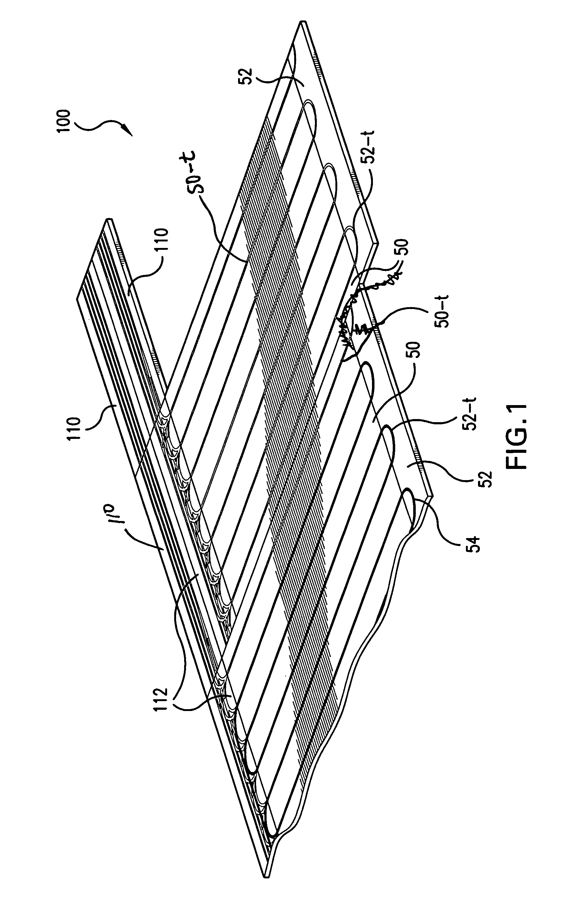
[0039]Further shown are the inventive bus panel 110 and a return / bus panel 112 of the present invention.

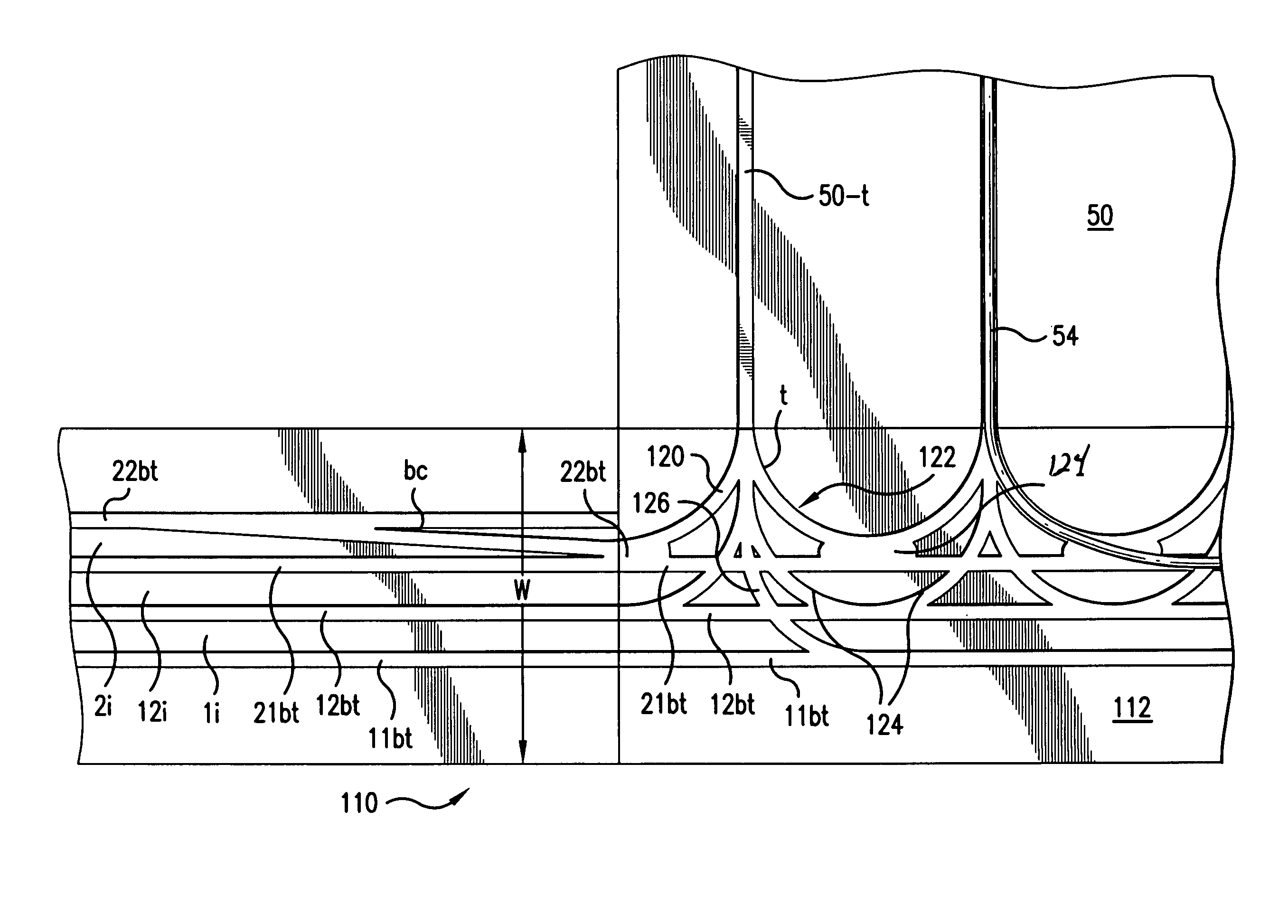
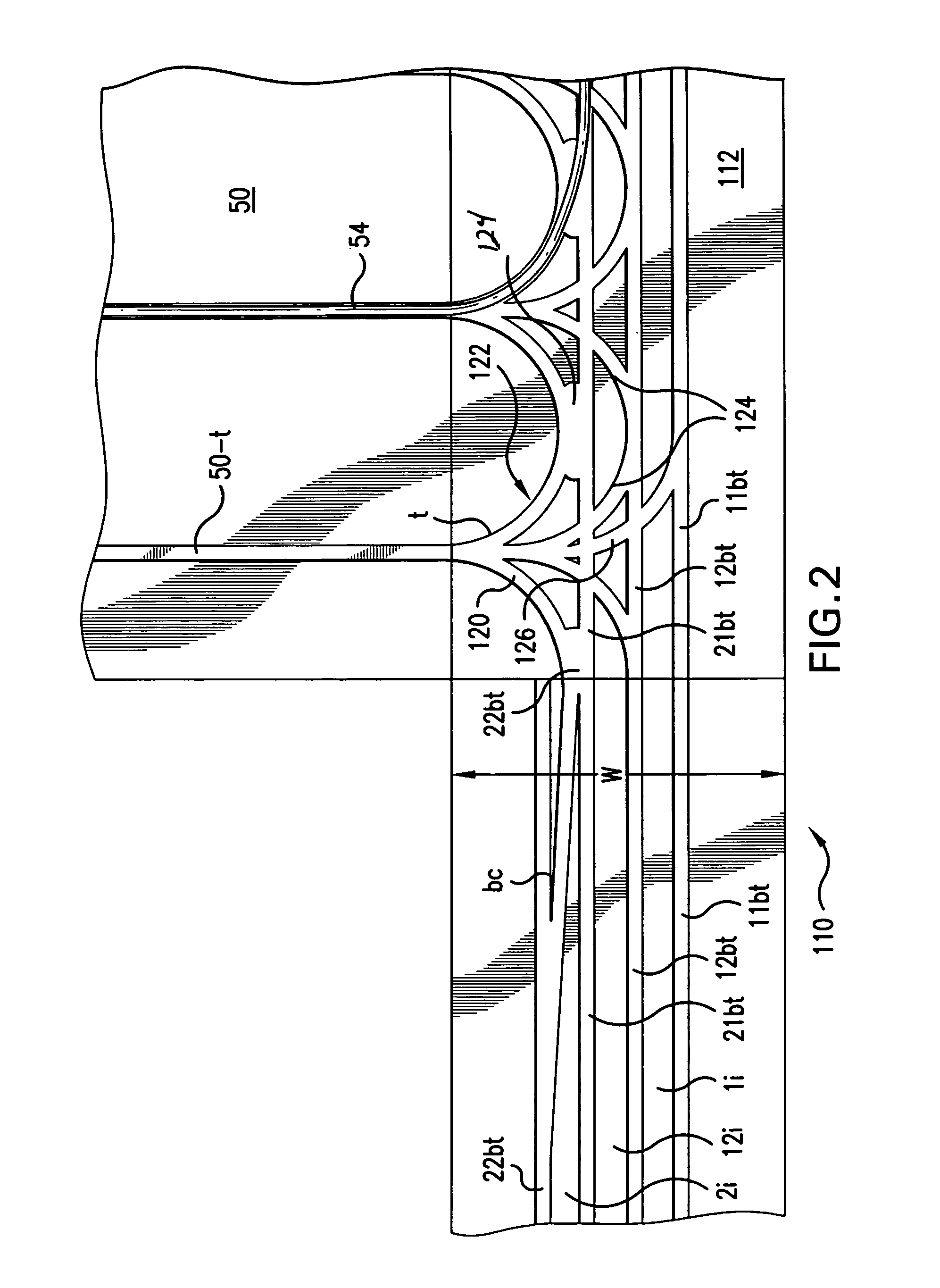
[0040]FIG. 2 is a close-up view showing the bus panel interfacing 110 with the return / bus panel 112 of the first embodiment of the present invention.

[0041]Specifically, the bus panel 110 comprises a loop-1, track-1 bus 11bt, a loop-1, track-2 bus 12bt, a loop-2, track-1 bus 21bt, and a loop-2, track-2 bus 22bt. Each of these bus tracks 11bt, 12bt, 21bt, 22bt extends along the entire length of the bus panel 110 in the preferred embodiment. Further, each of the bus tracks 11bt, 12bt, 21bt, 22bt extends parallel to each other. Further, islands: loop-1 island 1i, loop-12 island 12i, and loop-2 island 2i, are preferably provided separating each of the loop-1, track-1 bus 11bt, loop-1, track-2 bus 12bt, loop-2, track-1 bus 21bt, and a loop-2, track-2 bus 22bt from each other. Thus, the tubing 54 can be press fit into these separated tracks 11bt, 12bt, 21bt, 22bt during the installation ...

second embodiment

[0058]FIG. 4 shows a return / bus panel 210 according to a It comprises a series of U-turn or return tracks 222. These are tracks that allow the direction of the tubing to be changed 180 degrees. Typically, these return tracks 122 interface with tracks 50-t on lateral run panels 50.

[0059]The second embodiment return / bus panel also comprises a series of track buses 1bt, 2bt, 3bt, 4bt, 5bt, 6bt. These extend the length of the return / bus panel 210. Generally, the spacing of these bus tracks 1bt-6bt is close. Specifically, the width W is less than about 4 feet or 1.2 meters. In this way, four or more relatively closely spaced tracks are provided within a small distance. In the illustrated embodiment, at least 4 and preferably 5 or 6 or more laterally extending tracks 1bt, 2bt, 3bt, 4bt, 5bt, 6bt are disposed within a width W of less than 1 foot or 0.3 meters, or less, preferably within a width of panel 110 that is about 9.25 inches or 235 millimeters wide. Including any tubing routed in ...


PUM


Abstract

Modular panels for radiant thermal conditioning systems have special purpose bus tracks for routing tubing. Specifically, these tracks enable the routing of tubing, and specifically tubing from multiple circuits, in-plane, in the floor, ceiling, or walls. Specifically, multiple laterally extending tracks are provided for handling multiple circuits. A modular panel enables the interconnection between tubing held in bus tracks and the arcuate return tracks that are used for the tubing direction changes that are needed for creating serpentine paths of the tubing loops.

Description

RELATED APPLICATIONS[0001]This application claims the benefit under 35 USC 119(e) of U.S. Provisional Application No. 60 / 641,396, filed Jan. 5, 2005, which is incorporated herein by reference in its entirety.BACKGROUND OF THE INVENTION[0002]Hydronic radiant floor, wall, and ceiling heating are techniques for heating a space, such as a room in a dwelling or commercial building, usually for human and creature comfort. Typical hydronic heating systems require a supply of hot water or other fluid from a boiler, for example, and valves for controlling the quantity of the water from the supply that is fed to the heating loops, which include tubing and / or heating elements. It is often necessary to control the temperature of the water in the heating loops. For example, if the supply water temperature is about 180° F. (80° C.) for laundry, it must be modulated down to about 100° F. or 40° C. (or lower) for radiant systems.[0003]A suitable system for reducing and controlling the supply water ...

Claims


Application Information

Patent Timeline
Patent Type & Authority Patents(United States)
IPC IPC(8): F24D3/16
CPCF24D3/142F28F3/12F24D3/14Y02B30/00
Inventor FIEDRICH, JOACHIM
Owner FIEDRICH JOACHIM
Why Eureka
Try Eureka