Lock device for use in motor vehicle

a technology for locking devices and motor vehicles, which is applied in the direction of lock applications, roofs, carpet fasteners, etc., can solve the problems of increased striker receiving slots, troublesome work with which the operator has to handle the control lever, and the lock device of the above-mentioned publication fails to exhibit a satisfied play free standing of the seat in the in-use position, etc., to achieve convenient assembly and work.

Inactive Publication Date: 2011-10-04
MITSUI KINZOKU ACT
View PDF14 Cites 24 Cited by
  • Summary
  • Abstract
  • Description
  • Claims
  • Application Information

AI Technical Summary

Benefits of technology

[0008]Accordingly, it is an object of the present invention to provide a lock device for use in a motor vehicle, which is free of the above-mentioned drawbacks.
[0009]According to the present invention, there is provided a seat lock device which is readily assembled, assures a play-free posture of a retractable seat that is locked in the normal in-use position and assures an easier work with which an operator can handle the seat lock device.

Problems solved by technology

However, due to its inherent construction, the lock device of the above-mentioned publication fails to exhibit a satisfied play free standing of the seat in the in-use position.
However, in this case, the stroke of the control lever needed for releasing the cam part of the restraining member from the striker is inevitably increased which however brings about a troublesome work with which an operator has to handle the control lever.
This drawback becomes remarked when the size of the striker receiving slot is increased for the purpose of assuring insert of the striker into the slot.

Method used


Image

  • Lock device for use in motor vehicle
  • Lock device for use in motor vehicle
  • Lock device for use in motor vehicle

Examples


Embodiment Construction

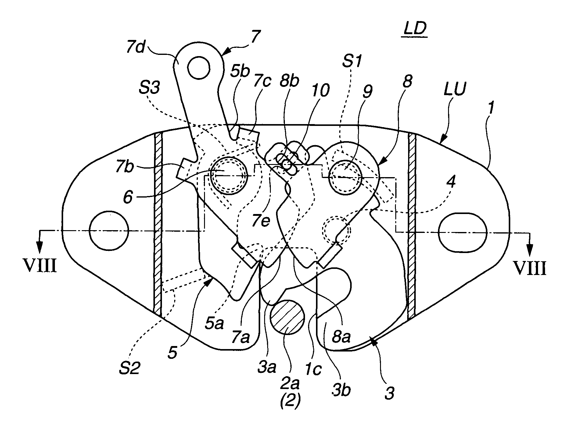
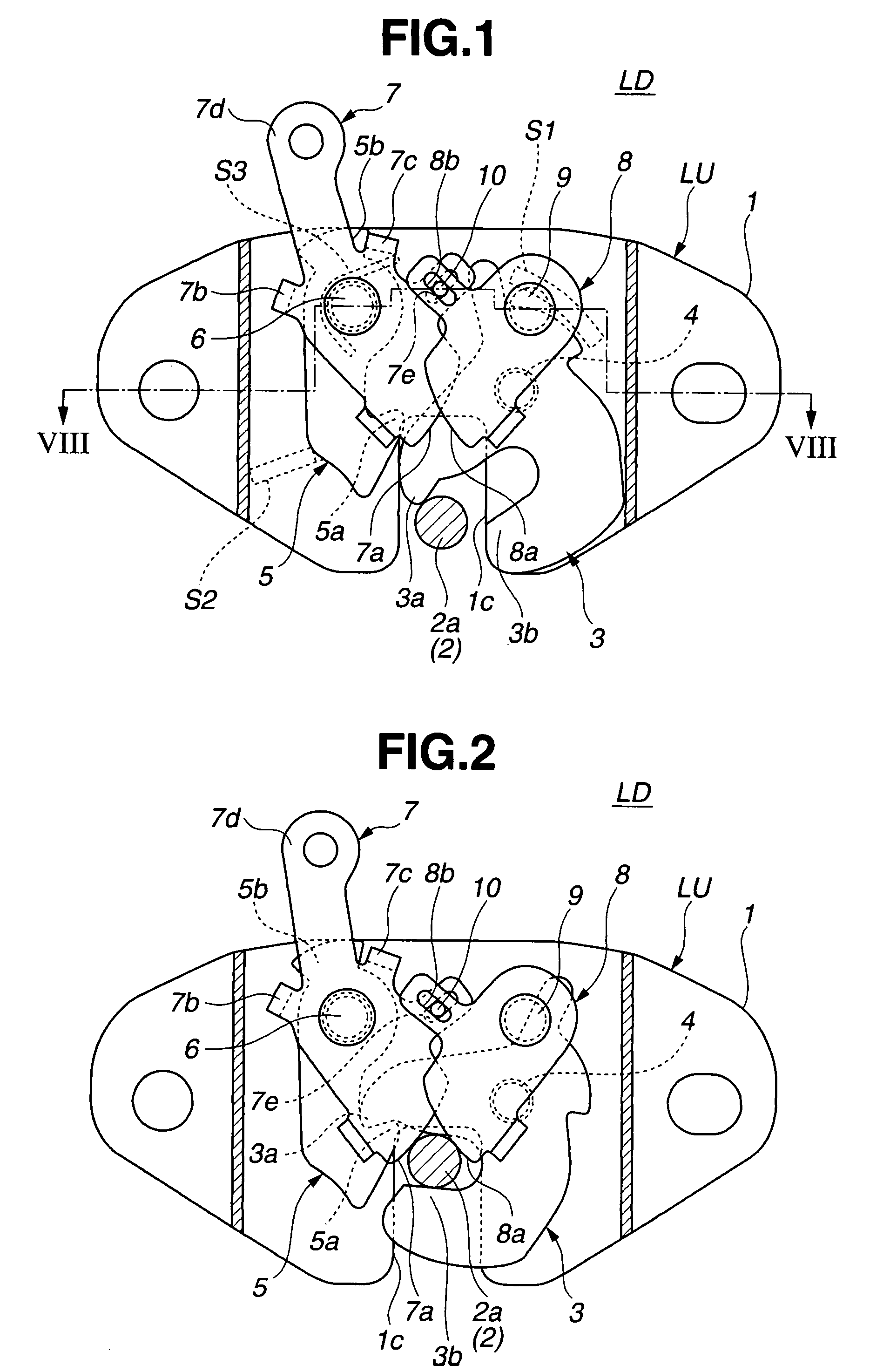
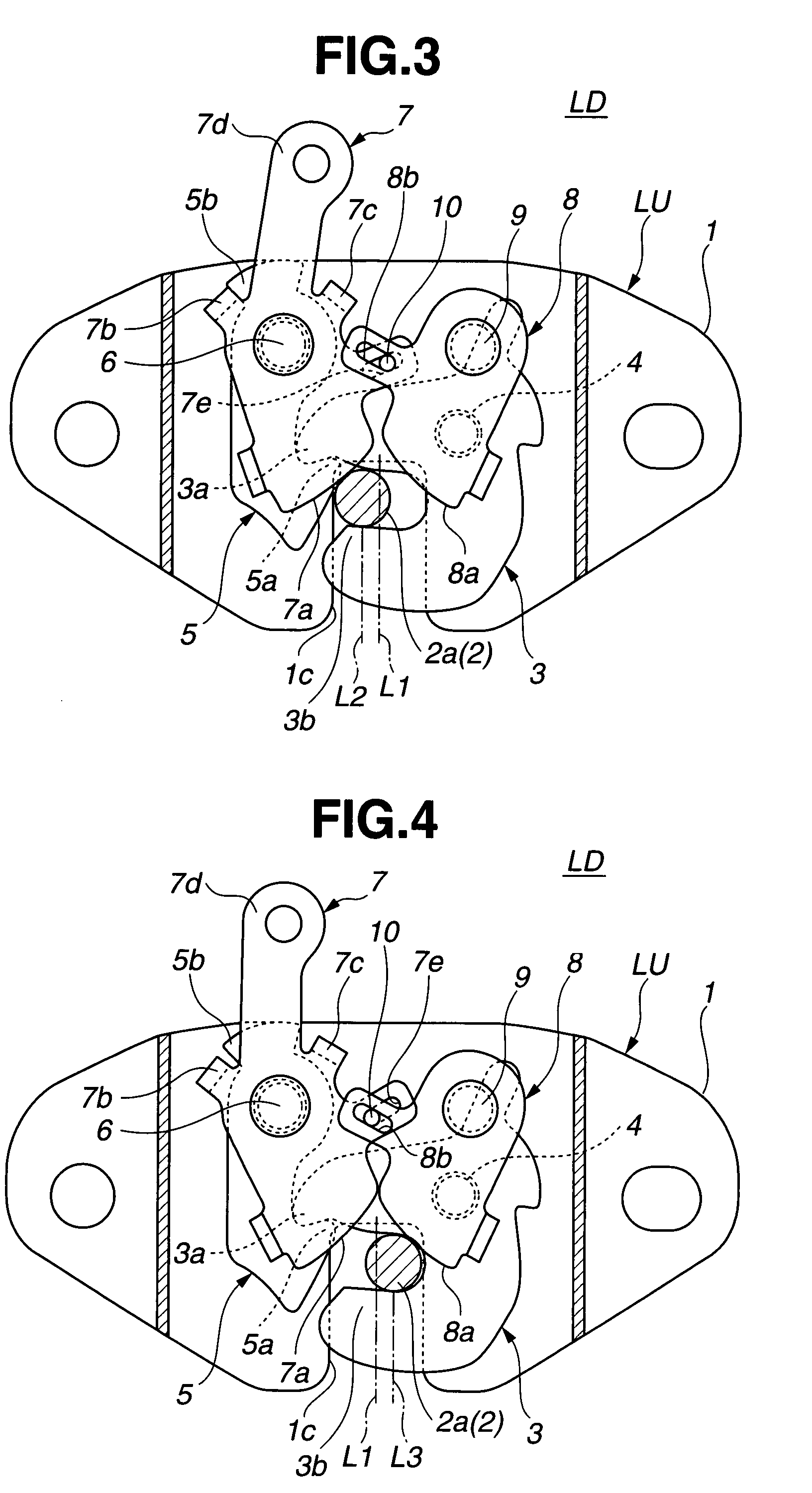
[0022]In the following, a lock device of the present invention will be described in detail with reference to the accompanying drawings.

[0023]For ease of understanding, various directional terms, such as, right, left, upper, lower, rightward and the like are used in the following description. However, such terms are to be understood with respect to only the drawing or drawings on which a corresponding part or portion is shown.

[0024]For the easy understanding of the lock device of the invention, firstly, the description will be directed to a case wherein the lock device is applied to a retractable seat of a motor vehicle which is shown in FIG. 9.

[0025]Referring to the drawing (viz., FIG. 9), there are shown two retractable seats 100 and 200 to which respective lock devices of the invention are practically applied.

[0026]It is to be noted that the seats 100 and 200 shown in the drawing are in their normal in-use position and each seat 100 or 200 is locked by the lock device of the inven...


PUM


Abstract

A pair of restraining plates are pivotally installed in a housing of a lock unit. The restraining plates have respective cam portions that are arranged to put therebetween a striker when the restraining plates are pivoted in respective given directions. A biasing member is arranged to bias one of the restraining plates to pivot in the given direction thereof, and a transmission mechanism is arranged between the restraining plates to induce a synchronized pivoting of the two restraining plates. Thus, when one of the restraining plates is pivoted in the given direction thereof, the other of the restraining plates is pivoted in the given direction thereof. With this arrangement, once the striker is locked by the lock unit, at least one of the cam portions of the restraining plates is pressed against the striker thereby to suppress or at least minimize undesirable play of the lock unit relative to the striker.

Description

BACKGROUND OF THE INVENTION[0001]1. Field of the Invention[0002]The present invention relates in general to lock devices for use in motor vehicles and more particularly to lock devices for locking a vehicle seat, vehicle door, engine hood, trunk lid, seat back and the like. More specifically, the present invention is concerned with a lock device that locks a retractable vehicle seat to a vehicle floor when the seat is pivoted back to its normal in-use position.[0003]2. Description of the Related Art[0004]In the field of motor vehicles, particularly one-box type passenger motor vehicles, there is a retractable type seat that is permitted to pivot up from its normal in-use position to an upper not in-use position for providing the vehicle floor with a larger free space. In such a seat, a lock device is usually provided for locking the seat when the same is returned back from the retracted position to its normal in-use position for the safety of passengers.[0005]One of the lock devices...

Claims


Application Information

Patent Timeline
Patent Type & Authority Patents(United States)
IPC IPC(8): E05C3/06B60N2/90E05B83/00B62D25/04B62D25/08E05B77/36E05B83/18E05B83/24E05B83/36E05B85/26
CPCB60N2/01583E05B83/16E05B85/26Y10S292/23Y10S292/43Y10T292/1047
Inventor SHIMURA, RYOJINAKAGOME, KATSUMI
Owner MITSUI KINZOKU ACT
Why Eureka
Try Eureka