Slidable constant velocity universal joint

a constant velocity, universal joint technology, applied in the direction of yielding couplings, clutches, shafts and bearings, etc., can solve the problems of deteriorating stability in torque transmission, problematic mounting operation involved, etc., to reduce contact friction between the members, reduce the contact range, and stabilize the attitude

Active Publication Date: 2011-10-04
NTN CORP
View PDF11 Cites 7 Cited by
  • Summary
  • Abstract
  • Description
  • Claims
  • Application Information

AI Technical Summary

Benefits of technology

[0009]In view of the above-mentioned problem, it is an object of the present invention to provide a slidable constant velocity universal joint which keeps an elastic member (coil spring) in a stable attitude even if a shaft makes an oscillating motion to thereby achieve an improvement in terms of stability in torque transmission.
[0011]When the shaft makes an oscillating motion with respect to the power transmission member, the forward end of the shaft is guided by the bearing member while in contact therewith. Thus, the elastic member is scarcely affected by the oscillating motion of the shaft, making it always possible to maintain a stable attitude.
[0013]Since the spherical convex surface portion of the cap member and the spherical concave surface portion of the bearing member are in contact with each other, the contact friction between the members is reduced, thus making it possible to effect smooth sliding. As a result, the influence of the oscillating motion of the shaft on the elastic member can be further mitigated.
[0015]Not the flat surface portion but the annular spherical convex surface portion of the cap member is held in contact with the bearing member. In this way, the cap member and the bearing member can be held in contact with each other in an annular fashion, thereby allowing stable sliding.
[0017]Due to this setting, it is possible to diminish the contact range between the cap member and the bearing member, thereby making it possible to further reduce the contact friction between the members.
[0018]According to the present invention, even if the shaft makes an oscillating motion with respect to the power transmission member, the elastic member is scarcely affected by the oscillating motion of the shaft, making it always possible to maintain a stable attitude. Thus, the elastic member (coil spring) is not bent as in the case of the slidable constant velocity universal joint shown in FIG. 6, making it possible to achieve an improvement in terms of stability in torque transmission.

Problems solved by technology

Further, the left-hand cross joint 100a has to be fixed to the power transmission shaft 120 by the bolt 105, and the mounting operation involved is problematic.
This may lead to deterioration in stability in torque transmission.

Method used


Image

  • Slidable constant velocity universal joint
  • Slidable constant velocity universal joint
  • Slidable constant velocity universal joint

Examples


Embodiment Construction

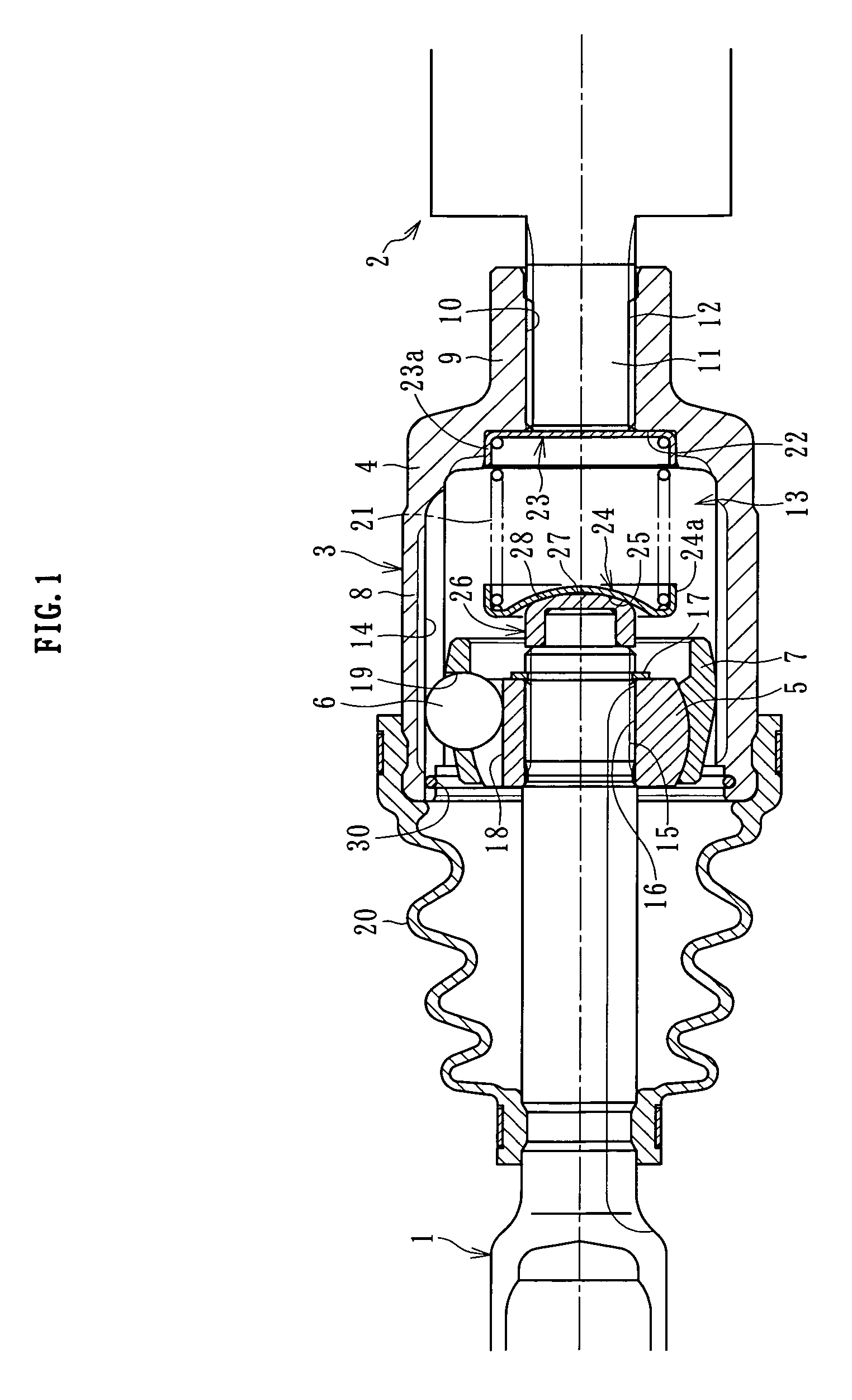
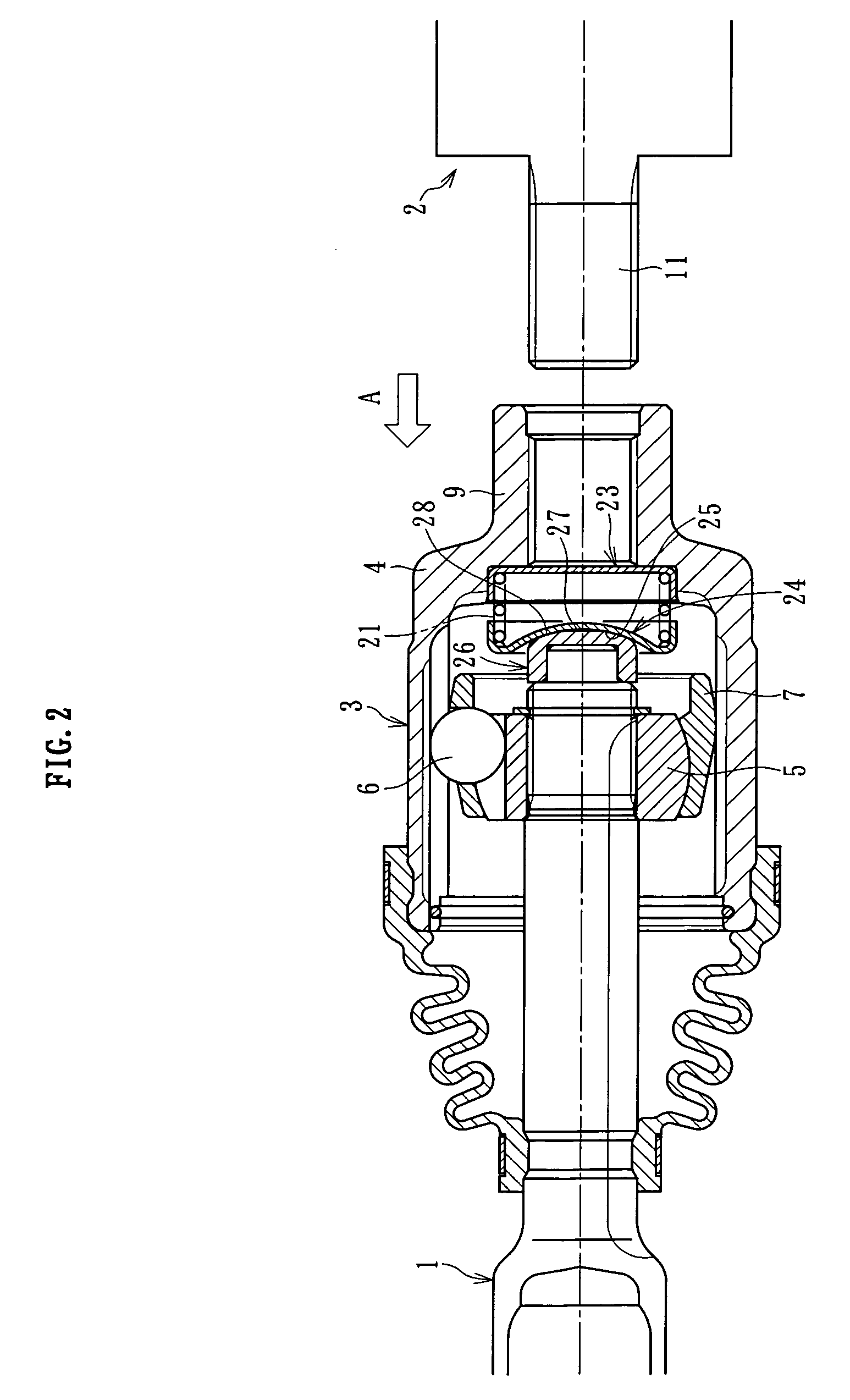
[0028]In the following, an embodiment of the present invention will be described with reference to the accompanying drawings.

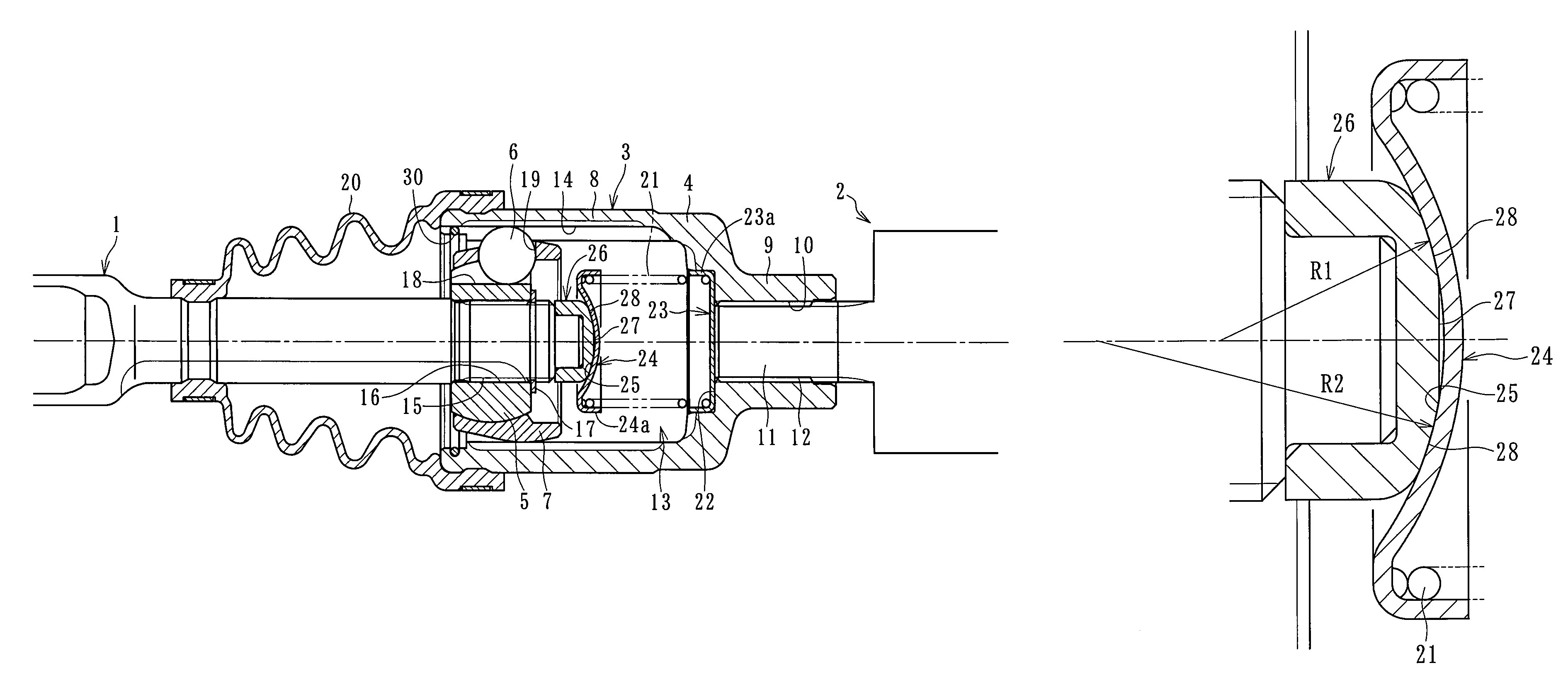
[0029]The present invention relates to a slidable constant velocity universal joint for use in a power transmission system, for example, a propeller shaft, used in a vehicle such as a passenger car or an agricultural tractor, in which both ends of a shaft arranged between two power transmission members, one constituting a driving shaft and the other a driven shaft, are respectively connected to two power transmission members so as to allow an oscillating motion. A pair of slidable constant velocity universal joints connected to both ends of this shaft are of a similar (symmetrical) structure (FIG. 8), so that solely the slidable constant velocity universal joint at one end of the shaft will be described.

[0030]As shown in FIG. 1, a slidable constant velocity universal joint according to the present invention is mainly composed of an outer ring 4, an inner ring ...


PUM


Abstract

A slidable constant velocity universal joint holds an elastic member (coil spring) in a stable attitude even if an associated shaft makes an oscillating motion, thereby achieving an improvement in terms of stability in torque transmission. The slidable constant velocity universal joint includes an outer joint member connected to a power transmission member, and an inner joint member connected to an end portion of a shaft, with torque transmission being possible between the outer joint member and the inner joint member while allowing angular displacement and axial displacement. At a forward end of the shaft, there is provided an elastic member for elastically urging the outer joint member toward the power transmission member, and, between the elastic member and the forward end of the shaft, there is interposed a bearing member for guiding the forward end of the shaft while in contact therewith.

Description

BACKGROUND OF THE INVENTION[0001]1. Field of the Invention[0002]The present invention relates to a slidable constant velocity universal joint for use in a power transmission system for automobiles, various industrial machines or the like and, more specifically, to a slidable constant velocity universal joint which is capable of transmitting rotary motion at constant velocity even when driving and driven shafts to be joined together are at an angle (operating angle) with respect to each other and which allows a relative axial movement between driving and driven shafts.[0003]2. Description of the Related Art[0004]As shown in FIG. 5, for example, in the power transmission system of a conventional vehicle such as an agricultural tractor, two power transmission shafts 120 and 130 and both ends of a propeller shaft 150 arranged between them are operationally connected with each other via cross joints 100a and 100b, respectively (see, for example, JP05-178105A and JP2003-300422A). The moun...

Claims


Application Information

Patent Timeline
Patent Type & Authority Patents(United States)
IPC IPC(8): F16D3/06
CPCF16D3/227F16D2003/22309F16D2003/2232F16D2300/22
Inventor TAKEKAWA, YASUAKI
Owner NTN CORP
Why Eureka
Try Eureka