Non-contact power charging system and control method thereof

a power charging and non-contact technology, applied in the direction of transformers, inductances, transportation and packaging, etc., can solve the problems of inability to charge at the same time, and inability to discharge immediately, so as to improve the charging efficiency and charge stably

Active Publication Date: 2011-10-04
INTEL CORP
View PDF21 Cites 34 Cited by
  • Summary
  • Abstract
  • Description
  • Claims
  • Application Information

AI Technical Summary

Benefits of technology

[0011]The present invention is also directed to improve charging efficiency by ensuring that a charging operation be performed at a stable voltage even if the non-contact power receiving apparatus moves by touching or displacement on the charge plate of the non-contact power transmission apparatus while being powered.
[0012]Further, the present invention is also directed to protect a battery cell from a magnetic field created by primary and secondary charge cores such that the battery cell can be stably charged.
[0028]As set forth above, the present invention can prevent the non-contact power receiving apparatus and the non-contact power transmission apparatus from being damaged by stopping power transmission when a foreign material is deposited on the charge plate.
[0029]Further, the present invention can also improve charging efficiency by ensuring that a charging operation be performed at a stable voltage even if the non-contact power receiving apparatus moves by touching or displacement on the charge plate of the non-contact power transmission apparatus while being powered.
[0030]Moreover, the present invention can also protect the battery cell from a magnetic field created by the primary and secondary charge cores such that the battery cell can be stably charged.

Problems solved by technology

However, when the charger and the batteries are connected or disconnected to replenish the electric power of the batteries with this connector supply system, an instant discharge may happen because of the potential differences between the charger connector and the battery connector.
Hence the foreign substances will be gradually gathered on both connectors and finally there may be a fire disaster.
Further, the collected humidity thereon will cause the discharge of the battery and other problems will be involved like the declining battery life, the low battery quality, and so on.
The existing non-contacting charging systems with the prior art can only be used to supply the electricity to the portable devices.
There are limited practical uses because they cannot be used in various alternatives.
Besides, if a metal is placed inside the effective radius of the generated magnetic field of the primary coil, there would be a lot loss of the electricity in the primary coil due to the changes of the magnetic field, so that non-contacting charging system may be damaged.

Method used


Image

  • Non-contact power charging system and control method thereof
  • Non-contact power charging system and control method thereof
  • Non-contact power charging system and control method thereof

Examples


Embodiment Construction

[0045]Hereinafter, the present invention will be described more fully with reference to the accompanying drawings, in which exemplary embodiments thereof are shown.

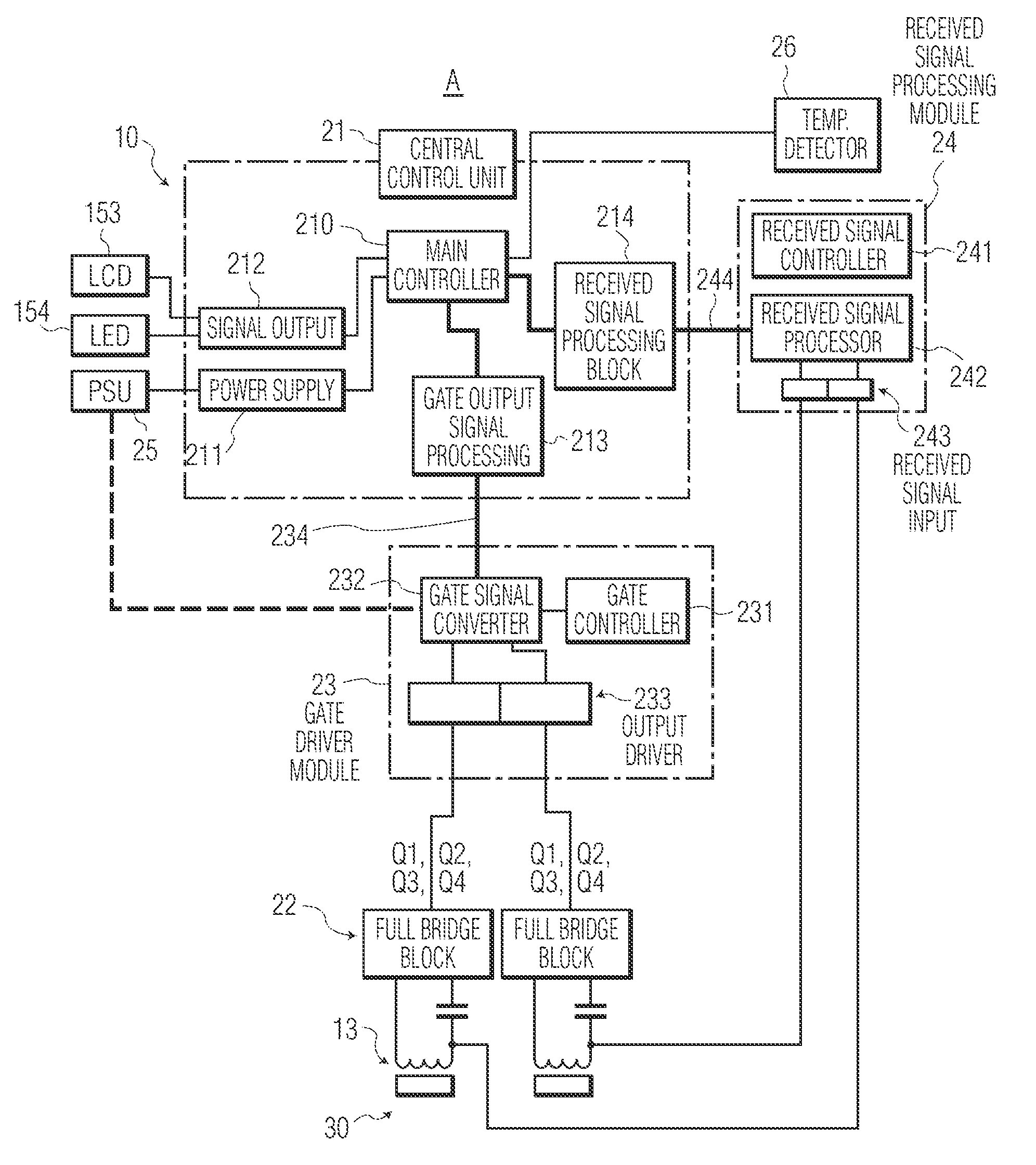
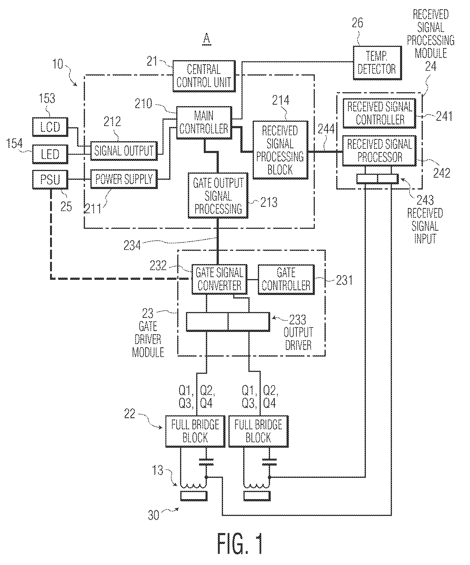
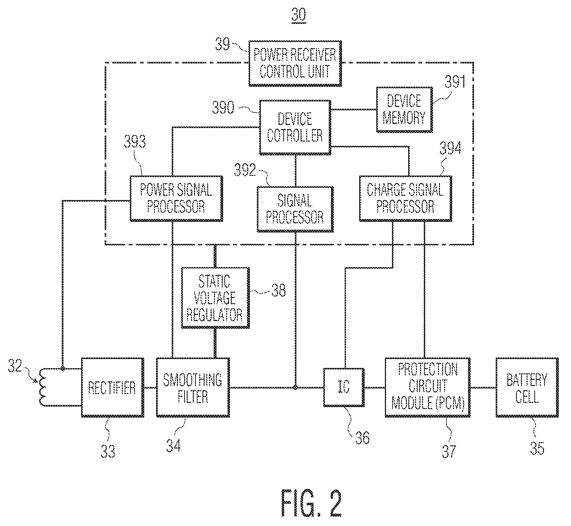
[0046]FIG. 1 is a schematic configuration view illustrating a non-contact power transmission apparatus of a non-contact power charging system in accordance with the present invention; FIG. 2 is a schematic configuration view illustrating a non-contact power receiving apparatus of the non-contact power charging system in accordance with the present invention; FIG. 3 is a flowchart illustrating a non-contact power transmission process of the non-contact power charging system in accordance with the present invention; FIG. 4 is a flowchart illustrating a non-contact power receiving process of the non-contact power charging system in accordance with the present invention; FIG. 5 is a control flow diagram illustrating a non-contact power transmission process of the non-contact power charging system in accordance with the presen...


PUM


Abstract

A non-contact power charging, in which power transmission can be interrupted when foreign materials are deposited on a charge plate of the non-contact power charging system. A charging operation can be continuously maintained at a stable voltage even if a non-contact power receiving apparatus moves by touching or displacement on the charge plate of the non-contact power charging system in the charging operation. Charging efficiency is improved.

Description

CLAIM OF PRIORITY[0001]This application claims the benefit of Korean Patent Application No. 10-2008-0015114 filed on Feb. 20, 2008, in the Korean Intellectual Property Office, the disclosure of which is incorporated herein by reference.BACKGROUND OF THE INVENTION[0002]1. Field of the Invention[0003]The present invention relates to a power charging system, and more particularly, to a non-contact power charging system and a control method thereof, in which power transmission can be interrupted when foreign materials are deposited on a charge plate of the non-contact power charging system, a charging operation can be continuously maintained at a stable voltage even if a non-contact power receiving apparatus moves by touching or displacement on the charge plate of the non-contact power charging system in the charging operation, and thus charging efficiency can be improved.[0004]2. Description of the Related Art[0005]Portable electronic devices, such as cellular phones, personal digital ...

Claims


Application Information

Patent Timeline
Patent Type & Authority Patents(United States)
IPC IPC(8): H02J7/00
CPCH02J7/025H02J50/10H02J50/80H02J50/60H02J50/12H02J50/70
Inventor JUNG, CHUN-KIL
Owner INTEL CORP
Why Eureka
Try Eureka