Optical part, lens barrel, and camera

a technology of optical parts and lenses, applied in the field of optical parts and lens barrels, can solve the problems of ghosting and flare, adversely affecting the formation of images, and the inability to shorten the distance between lenses, so as to improve optical performance and reduce size

Inactive Publication Date: 2011-10-04
PANASONIC CORP
View PDF25 Cites 31 Cited by
  • Summary
  • Abstract
  • Description
  • Claims
  • Application Information

AI Technical Summary

Benefits of technology

[0012]It is an object of the present invention to provide an optical part, a lens barrel, and a camera with which higher optical performance and a smaller size can both be achieved.

Problems solved by technology

Ghost, flare, and other such problems that adversely affect the formation of an image sometimes occur in cameras and other such optical devices.
When strong light is incident on an imaging optical system, part of the incident light is reflected by the lens surface in the imaging optical system, and this reflected light (harmful light) forms a false image, and this is what leads to ghost and flare.
When a light shielding sheet is used, however, the distance between lenses cannot be shortened, and furthermore space must be provided to fix the light shielding sheet, which impedes efforts at reducing the size of the lens barrel.
Meanwhile, when harmful light is blocked not just by a light shielding sheet, but also by inking, there may be cases when the harmful light cannot be effectively blocked.
The reason for this is that with inking, there tends to be variance in the coating film thickness, and the light shielding film is very thin, and that the original purpose of this ink is to reduce scattered reflection at the edges of the lens (the outer peripheral part of the lens), and the ink does not have high light shielding performance.
Therefore, even though a reduction in lens barrel size may be achieved, there are cases when harmful light cannot be blocked with inking alone, and the optical performance of the optical system deteriorates.

Method used


Image

  • Optical part, lens barrel, and camera
  • Optical part, lens barrel, and camera
  • Optical part, lens barrel, and camera

Examples


Embodiment Construction

[0039]Selected embodiments of the present invention will now be explained with reference to the drawings. It will be apparent to those skilled in the art from this disclosure that the following descriptions of the embodiments of the present invention are provided for illustration only and not for the purpose of limiting the invention as defined by the appended claims and their equivalents.

[0040]The lens barrel and camera according to the present invention will now be described with reference to the drawings.

[0041]1. Overview of Digital Camera

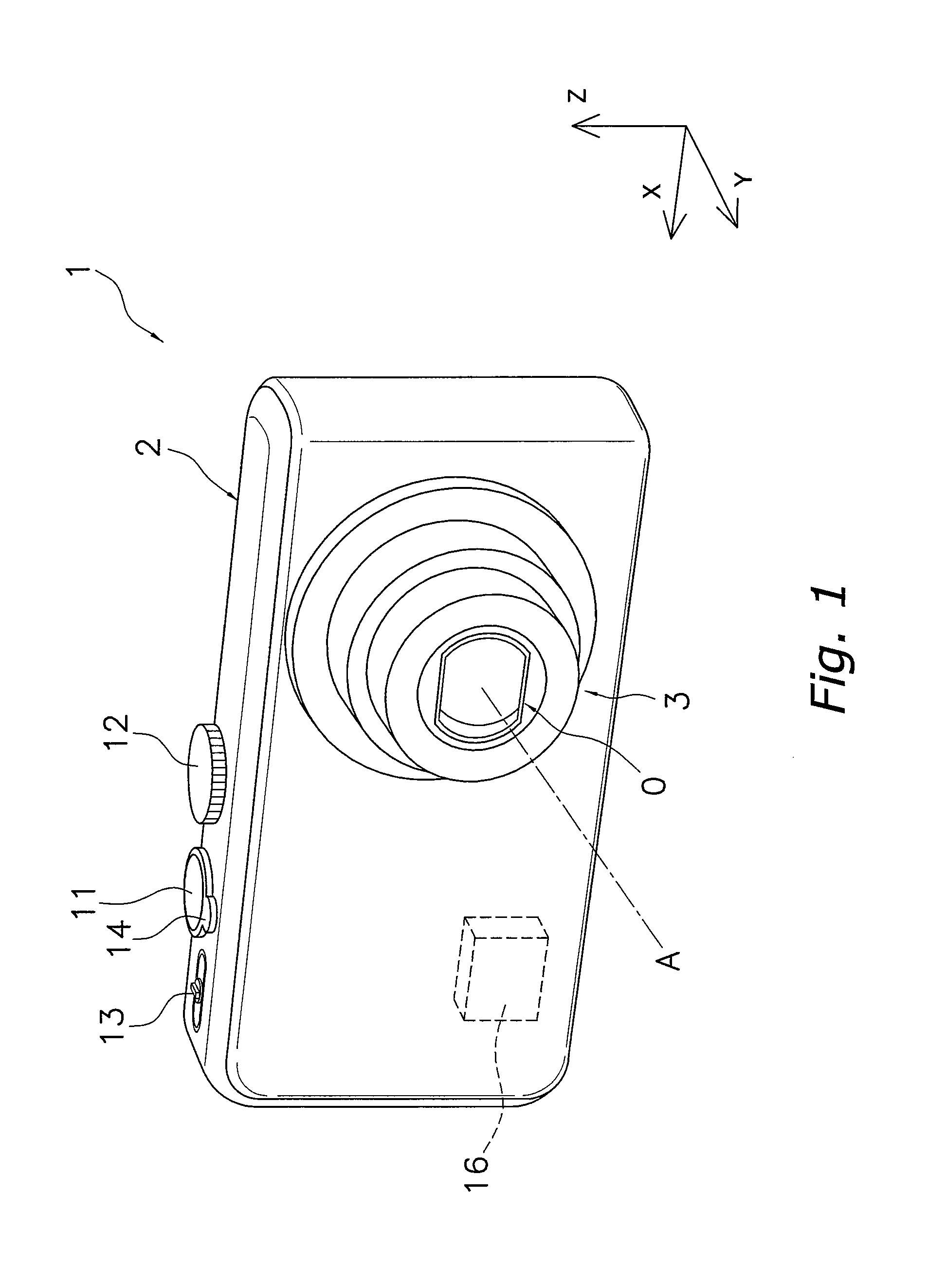
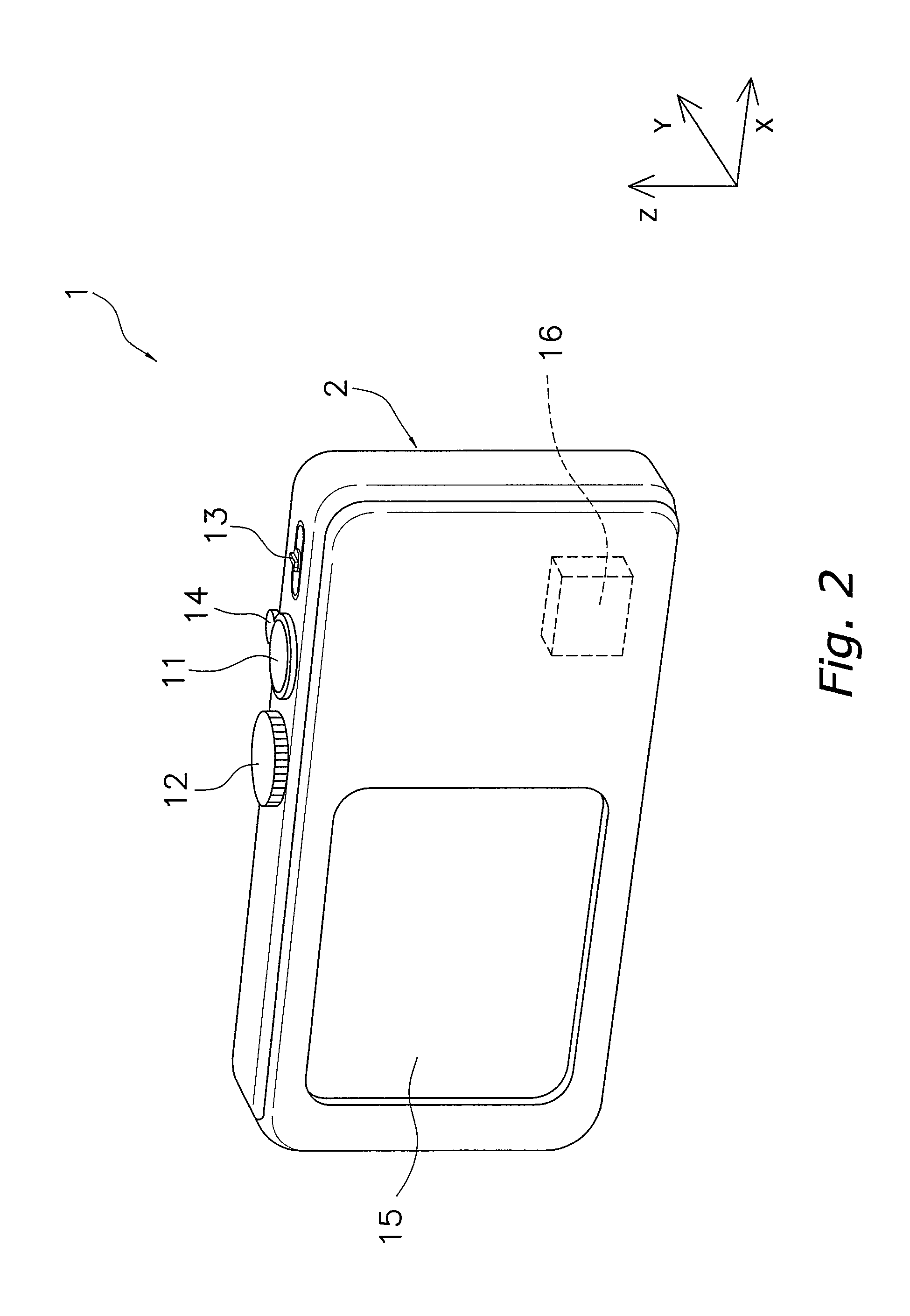
[0042]A digital camera 1 according to a preferred embodiment of the present invention will be described with reference to FIGS. 1 and 2. FIGS. 1 and 2 are schematic perspective views of the digital camera 1. FIG. 1 shows the situation when a lens barrel 3 is in an image capture state.

[0043]The digital camera 1 is a camera for acquiring an image of a subject. A multistage retractable lens barrel 3 is installed in the digital camera 1 in order to ...


PUM


Abstract

An imaging optical system O supported by a lens barrel 3 includes a second lens group G2. The second lens group G2 includes a fourth lens 54 and a black light shielding portion 54d formed by printing. The light shielding portion 54d is a film-shaped portion formed on the surface of the fourth lens 54, and blocks harmful light in the imaging optical system O. The light shielding portion 54d includes a synthetic resin. The light shielding portion 54d is disposed in a non-effective optical area of the fourth lens 54. The effective light path of the imaging optical system O is determined by the light shielding portion 54d.

Description

CROSS-REFERENCE TO RELATED APPLICATIONS[0001]This application claims priority to Japanese Patent Application No. JP2007-019051 filed on Jan. 30, 2007. The entire disclosures of Japanese Patent Application No. JP2007-019051 is hereby incorporated herein by reference.BACKGROUND OF THE INVENTION[0002]1. Field of the Invention[0003]The present invention relates to an optical part, a lens barrel, and a camera, and more particularly relates to an optical part, lens barrel, and camera having a light shielding portion for blocking out harmful light.[0004]2. Description of the Related Art[0005]Ghost, flare, and other such problems that adversely affect the formation of an image sometimes occur in cameras and other such optical devices. When strong light is incident on an imaging optical system, part of the incident light is reflected by the lens surface in the imaging optical system, and this reflected light (harmful light) forms a false image, and this is what leads to ghost and flare.[0006...

Claims


Application Information

Patent Timeline
Patent Type & Authority Patents(United States)
IPC IPC(8): G02B9/00
CPCG02B7/102G03B17/00G03B17/04
Inventor SHINTANI, DAI
Owner PANASONIC CORP
Why Eureka
Try Eureka