Prediction scheme for step wave power converter and inductive inverter topology

a technology of inductive inverter and prediction scheme, which is applied in the direction of ac-dc conversion, electric variable regulation, instruments, etc., can solve the problems of increasing the bulkiness of the step wave power converter, affecting the output and affecting the efficiency of the step wave a

Active Publication Date: 2011-10-04
SUSTAINABLE ENERGY TECH
View PDF111 Cites 45 Cited by
  • Summary
  • Abstract
  • Description
  • Claims
  • Application Information

AI Technical Summary

Problems solved by technology

Unfortunately, step wave power converters are bulky and require multiple transformers for each step.
To get better resolution in a three-phase AC waveform output, even more transformers must be added to the power converter, further increasing its bulkiness.
A further drawback of certain power converters is that the step wave AC output is generally blocky as a result of the mere addition of positive and / or negative block steps to form the AC waveform output.
Although blocky AC waveforms are acceptable for many applications, they are less than desirable for use in many modern electronic devices such as computers, televisions, etc., which perform better and last longer when power is supplied to them using a closely regulated AC power supply.
On the other hand predictive controllers require more computing resources and require a good knowledge of system parameters and can be sensitive to incorrect identification of load parameters.
Some predictive current control schemes also are not designed for step-wave inverters.

Method used


Image

  • Prediction scheme for step wave power converter and inductive inverter topology
  • Prediction scheme for step wave power converter and inductive inverter topology
  • Prediction scheme for step wave power converter and inductive inverter topology

Examples


Embodiment Construction

Current-Controlled Pulse Width Modulation (PWM) Scheme for Multilevel Grid-Tied Inverters

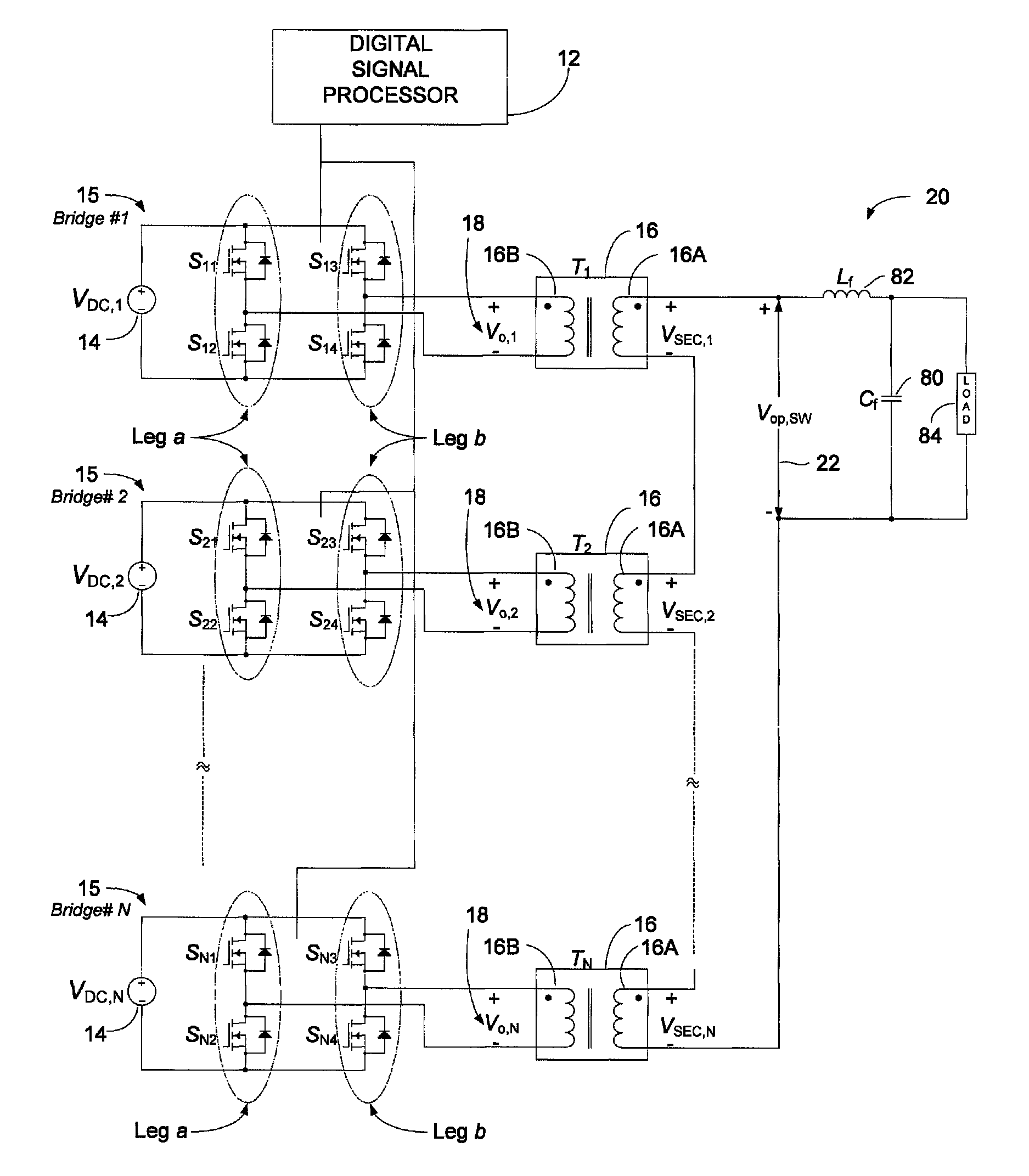
A novel current-control prediction scheme operates with multilevel grid-tied inverters. The prediction scheme can be used with any multilevel inverter topology which employs H-bridges where the outputs of multiple bridges are combined to obtain a multilevel output waveform. For instance, the prediction scheme can be used with a cascaded multilevel voltage-source inverter, and can also be used with inverters where the outputs of full-bridges, though isolated from each other, are combined through transformers. Specifically, the current-control prediction scheme can be implemented using the Step Wave Power Converter topologies described in U.S. Pat. No. 6,198,178, issued Mar. 6, 2001 which is herein incorporated by reference in its entirety.

Since-Phase Full-Bridge Voltage Source Inverter

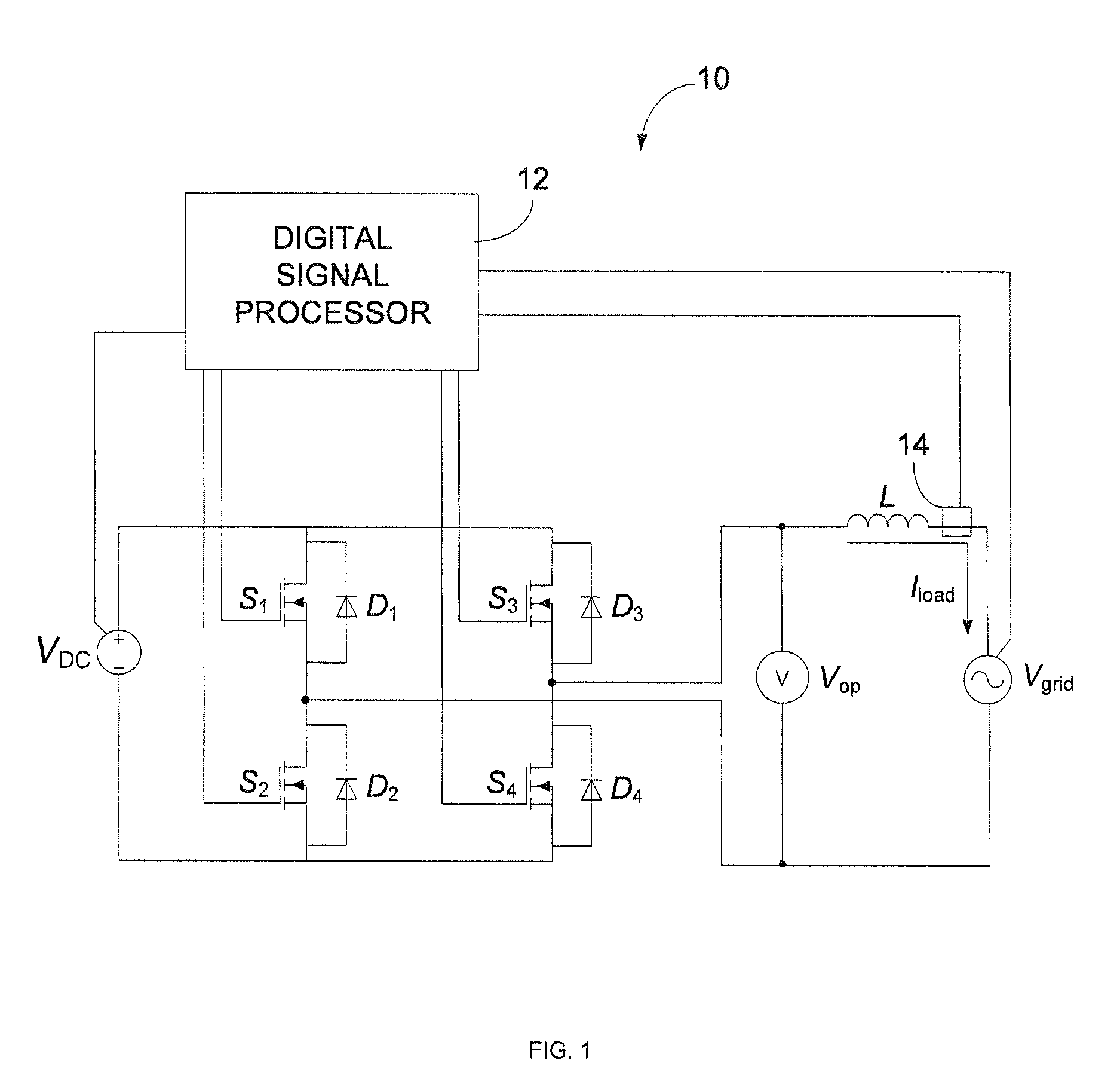
FIG. 1 shows a single-phase full-bridge inverter 10. Two pairs of transistor switches S1 / S2 and S3 / S4 are each co...


PUM


Abstract

A step wave power converter comprises multiple different bridge circuits configured to convert DC voltage inputs into AC voltage outputs. A controller is configured to estimate an average voltage output from the multiple different bridge circuits for controlling the current output from the multiple different bridge circuits. The number of bridge circuits needed to provide the estimated average output voltage is identified and the identified bridge circuits controlled during a next switching period to generate a combined inverter output voltage that corresponds with the estimated average output voltage.In another embodiment, one or more transformers are associated with the different bridge circuits. Inductors are coupled between the bridge circuits and the primary windings of the associated transformers. The inductors filter the current output from the bridge circuits prior to feeding the current into the transformers.

Description

FIELD OF INVENTIONThis application relates generally to power conversion.BACKGROUNDVarious step wave power converters exist for transforming a DC voltage into a step wave AC output. Step wave power converters use different transformers for each step of the step wave output. The primary windings of the different transformers are electrically coupled to the DC power source through bridge circuits. Gates in the bridge circuits control the flow of current through the primary windings to produce steps of the AC output from the secondary winding.Unfortunately, step wave power converters are bulky and require multiple transformers for each step. Also, the total number of steps in the AC output directly correspond with the number of transformers used for producing the output. To get better resolution in a three-phase AC waveform output, even more transformers must be added to the power converter, further increasing its bulkiness.A further drawback of certain power converters is that the ste...

Claims


Application Information

Patent Timeline
IPC IPC(8): H02M7/5387H02M3/24
CPCH02M7/49H02M7/53873H02M2001/0077H02M1/0077
Inventor SACHDEVA, RISHIMORASH, RUSSELL JACK
Owner SUSTAINABLE ENERGY TECH
Why Eureka
Try Eureka