Rectifier circuit

a rectifier circuit and rectifier technology, applied in the direction of power conversion systems, efficient power electronics conversion, climate sustainability, etc., can solve the problems of reducing generator efficiency and power conversion efficiency, and achieve the effect of low energy conversion loss

Inactive Publication Date: 2010-07-01
TEXAS INSTR INC
View PDF4 Cites 53 Cited by
  • Summary
  • Abstract
  • Description
  • Claims
  • Application Information

AI Technical Summary

Benefits of technology

[0008]It is a general object of the invention to provide a rectifier circuit that can be used in low power energy harvesting systems with a low energy conversion loss.

Problems solved by technology

Thus, there is always a voltage drop of twice the forward voltage Vforward of the diodes, which reduces power conversion efficiency.
This capacitor is connected to the output of the AC generator via the rectifier bridge which leads to an impedance mismatch between AC generator, bridge rectifier and capacitor, thus also reducing generator efficiency.

Method used


Image

  • Rectifier circuit
  • Rectifier circuit
  • Rectifier circuit

Examples


Embodiment Construction

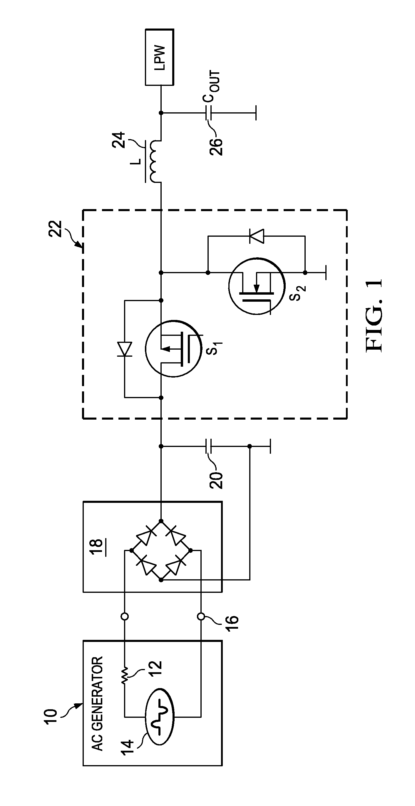
[0023]FIG. 1 shows in a simplified schematic an energy harvesting system of the state of the art. An AC generator 10 comprises a generator impedance 12 and outputs an AC voltage with a waveform as indicated in a simplified manner under reference sign 14. An output 16 of the AC generator 10 is connected to an input of a full bridge rectifier 18 formed by four diodes. A storage capacitor 20 is connected with its two terminals to the output of the rectifier diode bridge. One terminal of the storage capacitor 20 is further connected to ground. The other terminal of the storage capacitor 20 is connected to a buck converter 22. The buck converter comprises two switches S1 and S2 formed by MOS FET transistors. The terminal of the storage capacitor 20 which is coupled to the buck converter 22 is connected to a drain of transistor S1 and the source of transistor S1 is connected to a drain of transistor S2. A source of transistor S2 is connected to ground. Transistors S1 and S2 together with ...


PUM


Abstract

A rectifier circuit for use in an energy harvesting application in which mechanical energy is converted into electrical energy by using an AC generator using an active rectifier bridge with a pair of input terminals adapted to be connected to an output of the AC generator and a pair of output terminals, an inductor connected across the output terminals of the active rectifier bridge and a storage capacitor. A pair of output switches selectively connects the storage capacitor across the inductor. A controller controls the active rectifier bridge and the pair of output switches such that in successive switching cycles within any half wave of AC input voltage from the output of the AC generator the inductor is first loaded by current from the output of the AC generator and then discharged into the storage capacitor. An energy harvesting system which uses an AC generator for generating electrical energy out of mechanical energy, a rectifier circuit which is connected with the input to the output of the AC generator and a low power wireless system as application unit. A method of rectifying an AC output voltage of an AC generator for use in an energy harvesting application.

Description

CROSS-REFERENCE TO RELATED APPLICATIONS[0001]This patent application claims priority from German Application No. 10 2008 064 402.1, filed Dec. 22, 2008, the entirety which is incorporated herein by reference.FIELD OF THE INVENTION[0002]The invention relates to a rectifier circuit for use in an energy harvesting application and a process of rectifying an AC output voltage. More particularly, the invention relates to a rectifier circuit comprising an active rectifier bridge.BACKGROUND OF THE INVENTION[0003]In low power energy harvesting systems, inductive or piezo electric generators are used to generate electrical energy out of mechanical energy such as vibrations, pushbuttons press etc, in order to power low power wireless circuits (LPW systems).[0004]The electric generators used to generate electrical energy out of mechanical energy are AC voltage generators. They behave like an AC generator with internal impedance. The AC voltage output depends on the kind of mechanical-electrical...

Claims


Application Information

Patent Timeline
Patent Type & Authority Applications(United States)
IPC IPC(8): H02M7/12
CPCH02M7/219Y02B70/1408Y02B70/10
Inventor MATZBERGER, MARKUSWAGENSOHNER, KONRADBAYER, ERICH-JOHANN
Owner TEXAS INSTR INC
Why Eureka
Try Eureka