
Inorganic-Organic Hybrid Nanocomposite Antiglare and Antireflection Coatings

a technology of nanocomposites and nanocomposites, which is applied in the direction of synthetic resin layered products, instruments, transportation and packaging, etc., can solve the problems of surface reflection, high undesirable effects, and high production costs, and achieve the effect of improving the anti-reflection

Inactive Publication Date: 2009-01-01
OPTIMAX TECHNOLOGY CORPORATION
View PDF3 Cites 55 Cited by
  • Summary
  • Abstract
  • Description
  • Claims
  • Application Information

AI Technical Summary

Benefits of technology

[0012]In one embodiment, the present anti-reflection coating containing F-silica particles and inorganic-organic hybrid matrix is based on a simple self-assembly process and the coating components can be cured subsequently by heat, UV-radiation, or both together.
[0013]In one embodiment, the process starts with a homogeneous suspension of F-silica particles, soluble functionalized silica sol, dispersing agent, organic monomer / oligomer, and initiator prepared in lower alcohols. The coating may be applied to the substrate using well known techniques such as reverse roll coating, wire-wound rod and dip coating methods. During the coating application procedure, preferential evaporation of the alcohol progressively enriches the non-volatile coating compositions on the depositing substrate. The dispersed fluorocarbon surface modified silica particles, because of their low-energy surface, migrate to the surface of the coating layer, which leads to the lowest system energy of the coating layer. When fluorinated silica particle concentration is high enough, the accumulated particles completely cover the surface of the coating, and form a coating layer with a gradient refractive index, as described in commonly assigned, co-pending application Ser. No. 10 / 514,018, filed Nov. 10, 2004 and published Apr. 1, 2004, under WO2004 / 027517, the entire disclosures of which are incorporated herein in their entirety by reference thereto, and which enhances the anti-reflection effect. At the same time, some of F-silica particles aggregate to form particle clusters with domain size at the same length scale as the wavelength of the visible light. The particle clusters on the coating surface scatter the reflected light and then offer antiglare effectiveness.
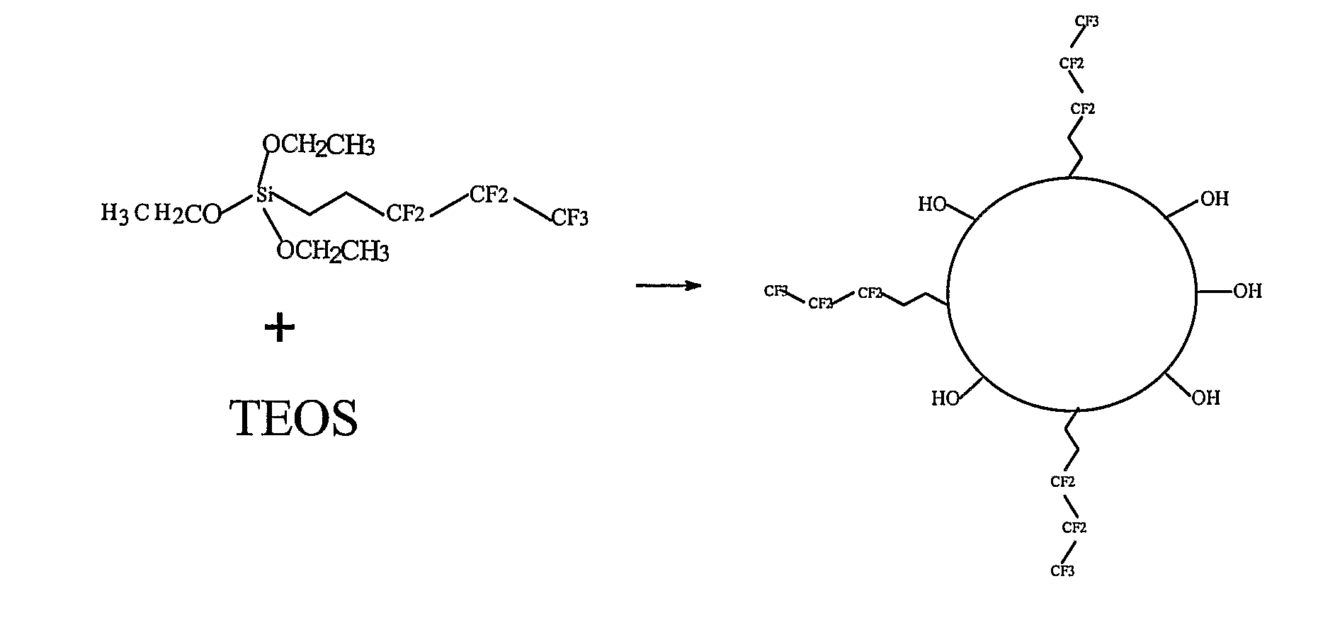
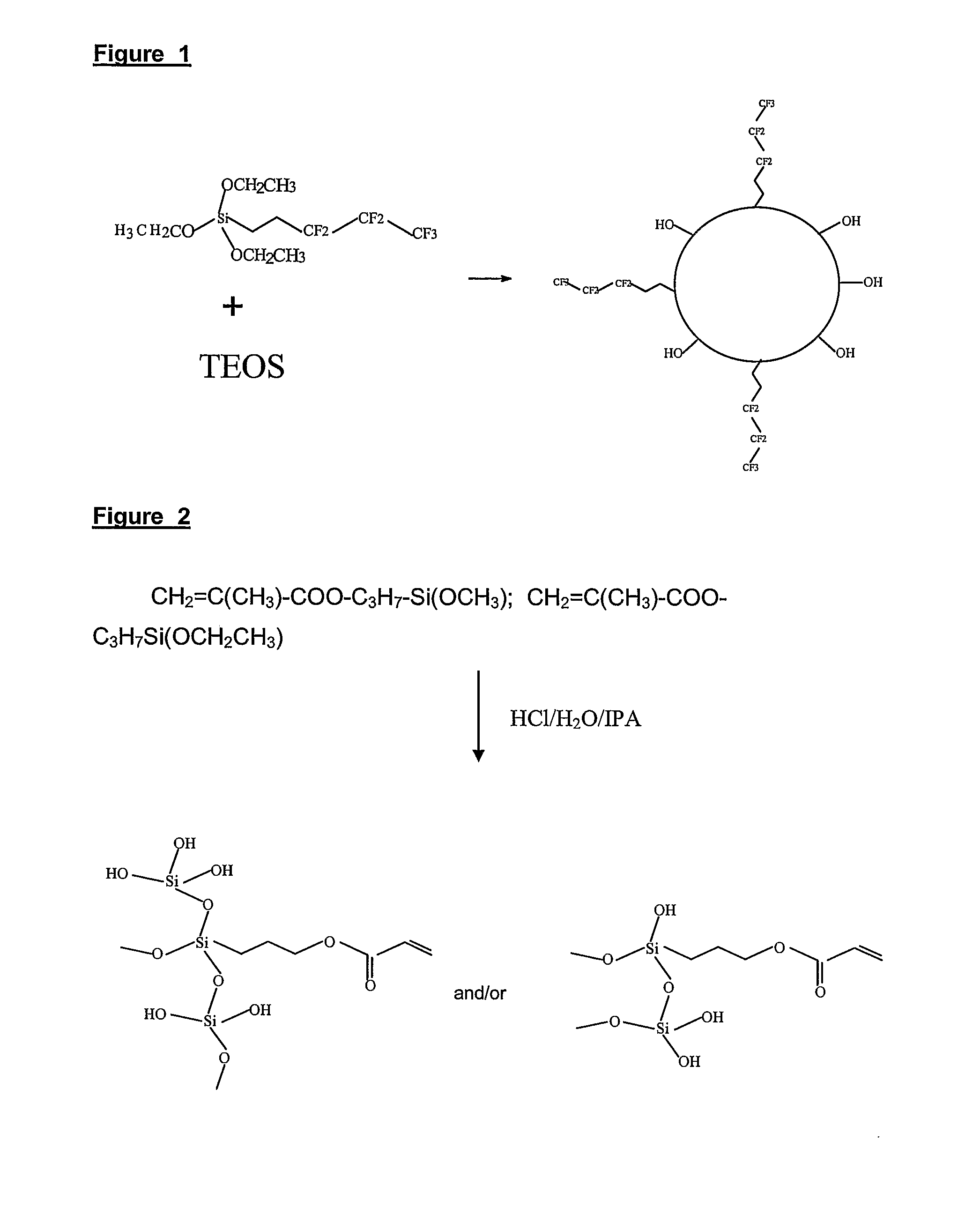
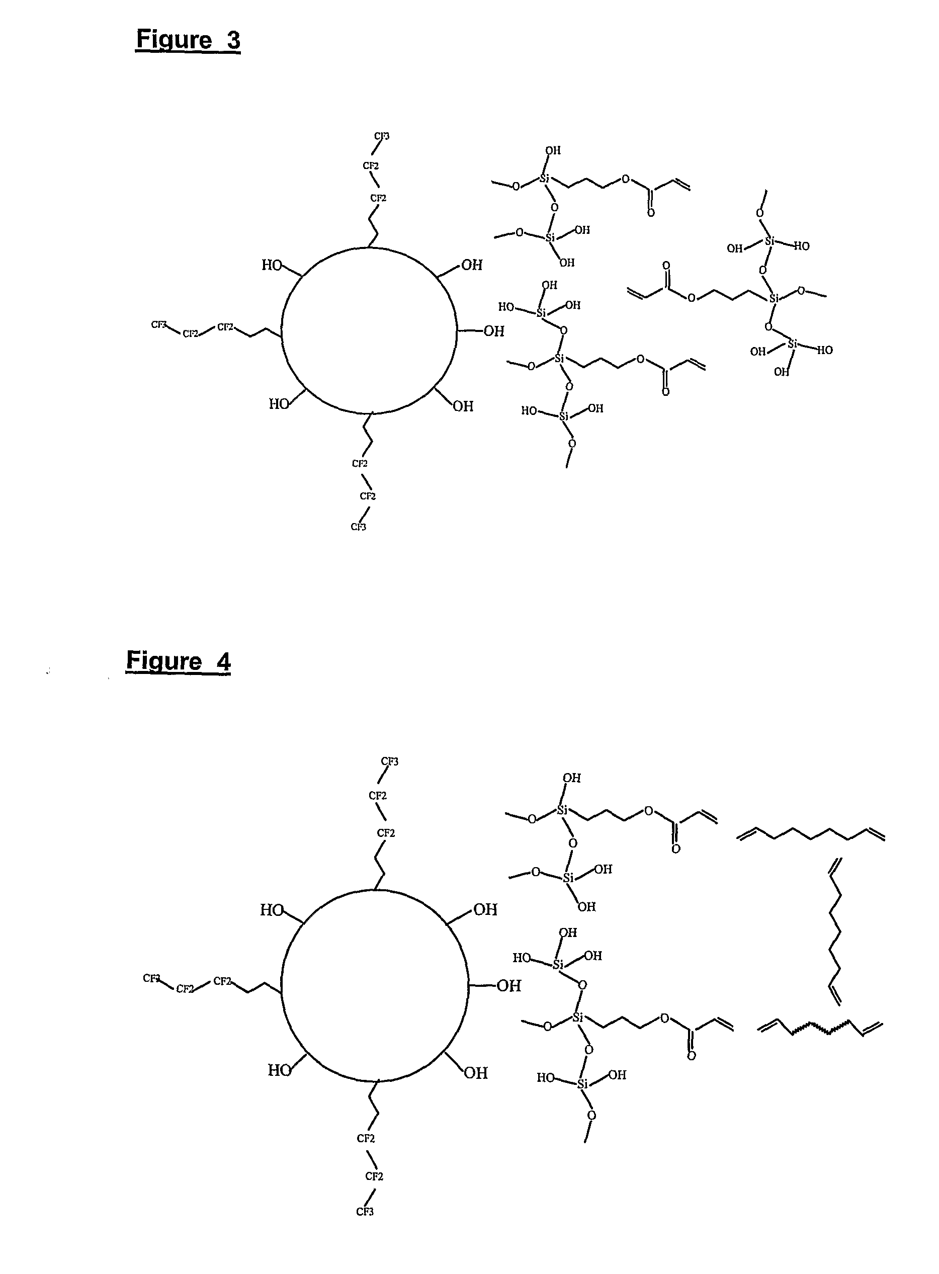
[0027]The functionalized silica sol can be used as the binder or matrix in the present AGAR coating compositions. The silica sol acts as both binder for the F-silica particles and hard coating matrix after being cured. The primary silica entity in the sol is partially condensed silica oligomer. Representative chemical structures of the oligomers are shown in FIG. 2 for Scheme 2. Besides organic functional groups, a large amount of silanol groups exist on the silica oligomer. These silanol groups will further react with each other or with other functional groups under appropriate conditions to form a crosslinked network. In embodiments of the present invention, the F-silica particle is another desired component in the coating composition. After the evaporation of solvent, the coating layer with the structure as shown in FIG. 3 (Scheme 3) automatically forms on the substrate as the result of self-assembly of coating components. In this embodiment, the surface of the F-silica particle has been modified with fluoroalkyl group(s). However, there are generally still a large number of silanol groups remaining on the particle surface. The subsequent condensation of these silanol groups on the F-silica particle with the silanol group on silica oligomer will chemically link the F-silica particle to the organic silica sol. After curing with UV-radiation or heat, the organic silica sol becomes the coating matrix. The chemical bonding between F-silica particles with the coating matrix will significantly increase the mechanical properties of the coating.

Problems solved by technology

The detrimental effects from surface reflections, whether it is attributed to a reduced contrast ratio or an interfering image of an external object, are highly undesirable, and must be minimized.
Furthermore, for achieving such a destructive interference, each layer's thickness must be controlled within the precision of several to ten nanometers; making its production (normally by a vapor deposition process) much more difficult and more expensive than that achievable by an ordinary coating process.
While a multi-layered AR coating by vapor deposition is effective in reducing reflection intensity, it is not effective due to the flatness of the top surface in diffusing the (reduced) specular reflection.
When used under bright outdoor lighting conditions, an AR coating, unless able to achieve 100% reduction in reflection across the whole visible spectrum, may still show a weak and sometimes even colored image of a bright external object.
Anti-marring properties of the coating is another critical issue for display monitor panel or optical lenses applications.
29, No. 7, 993 (1982); DE 19708776 (1998)), have the same problem in that the coating surface is not durable and is easily abraded or scratched.
Synthetic organic polymer coatings based upon acrylic or terephthalate resins have generally good optical properties, but have their limits as hard coating to prevent abrasion or scratch marring.
Inorganic coatings produced by gas phase or vacuum deposition (CVD, PVD), have relatively good abrasion or scratch resistance, but they are expensive to manufacture and the adhesion between the coating layer and substrate is often poor because of the different thermal expansion coefficients of the coating and the substrate.

Method used


Image

  • Inorganic-Organic Hybrid Nanocomposite Antiglare and Antireflection Coatings
  • Inorganic-Organic Hybrid Nanocomposite Antiglare and Antireflection Coatings
  • Inorganic-Organic Hybrid Nanocomposite Antiglare and Antireflection Coatings

Examples


example 1 and example 2

Preparation of Fluorocarbon Modified Silica Particles

example 1

[0041]In a reaction vial, 100 ml isopropanol (IPA), 14 ml tetraethoxysilane (TEOS) and 6 ml tridecafluoro-1,1,2,2-tetrahydrooctyl)triethoxysilane (F-TEOS) were added and mixed with a magnetic stirrer at a high speed for two minutes. While stirring, 7.5 ml deionized water and 5 ml concentrated ammonia solution (NH3 28-30 wt % in water) were added into the mixture. The mixture was stirred over a period of 30 to 240 minutes. The initially clear mixture became a translucent suspension. The suspension was aged for two days and then the particle size was determined by laser light scattering. The medium for particle sizing was ethanol. The particle suspensions were treated by ultrasound for 5 to 10 minutes before particle sizing. The fluoro-content in the particles was calculated based on the molar ratios of the reactants.

[0042]The average particle diameter prepared from above procedure is about 120 nm. The molar ratio of F-containing silica to pure silica in the particles is 20:80.

example 2

[0043]In a reaction vial, 100 ml isopropanol, 14 ml TEOS and 6 ml F-TEOS were added and mixed with a magnetic stirrer at a high speed for two minutes. During the stirring, 14.5 ml of deionized water and 5 ml concentrated ammonium hydroxide solution (NH3 28-30 wt %) were added to the mixture. The mixture was stirred over a period of 30 to 240 minutes. The initially clear mixture develops into an opaque white suspension. The suspension was subsequently aged for two days and then the particle size was determined by laser light scattering. The particle size is around 250 nm. The molar ratio of F-containing silica to pure silica in the particles is 20:80.


PUM

PropertyMeasurementUnit
Particle sizeaaaaaaaaaa
Viscosityaaaaaaaaaa

Abstract

Embodiments of this disclosure relate to compositions, and a method of making UV or heat curable anti-reflection and anti-glare hard coatings. Such coatings may be useful, for example, for simultaneously improving transmission and preventing undesired visible reflection on various monitor or display panels and optical lenses. For the panels with plastic covers, the coating will also improve the surface mechanical properties such as abrasion and scratch resistance.

Description

CROSS-REFERENCE TO RELATED APPLICATION[0001]This application claims benefit of U.S. Provisional Application No. 60 / 656,096 filed Feb. 25, 2005. This application, in its entirety, is incorporated herein by reference.BACKGROUND OF THE INVENTION[0002]With a tremendous surge in the use of hand-held telecommunication or computerized apparatuses such as cellular phones, palm devices or portable on-line tools, their respective display devices must pass much harsher quality and endurance tests commensurate to their use in an outdoor environment. Consequently, their top functional coating, whether for the purpose of improving the image quality or protecting the device surface, must be significantly upgraded to meet new challenges.[0003]Compared with a desk-top unit, these smaller devices, including laptop computers, are more likely to be operated under a less controllable lighting environment. The reflection of the external lighting from the top surface of a display, even though representing...

Claims


Application Information

Patent Timeline
IPC IPC(8): B32B5/16B32B27/06C08K9/10
CPCC08L83/06G02B1/111Y10T428/259C08L2666/54Y10T428/31507
Inventor ZHANG, RUIYUNWU, XIAODONGYANG, JIN-MING
Owner OPTIMAX TECHNOLOGY CORPORATION
Learn More