Controller having output current control for a power converter

a power converter and output current controller technology, applied in the direction of electric variable regulation, process and machine control, instruments, etc., can solve the problems of increasing the cost of the power converter, reducing the cost of the converter, and consuming a lot of power loss

Active Publication Date: 2008-08-19
SEMICON COMPONENTS IND LLC
View PDF9 Cites 58 Cited by
  • Summary
  • Abstract
  • Description
  • Claims
  • Application Information

AI Technical Summary

Problems solved by technology

However, a considerable power loss is normally consumed due to the output current detection circuit, particularly as the output current is high-level.
Besides, this output control circuit takes a space of the PCB (print circuit board) and increases the cost of the power converter.
Therefore, the power converter saves the power losses by the switching current control instead of the output current control.

Method used


Image

  • Controller having output current control for a power converter
  • Controller having output current control for a power converter
  • Controller having output current control for a power converter

Examples


Embodiment Construction

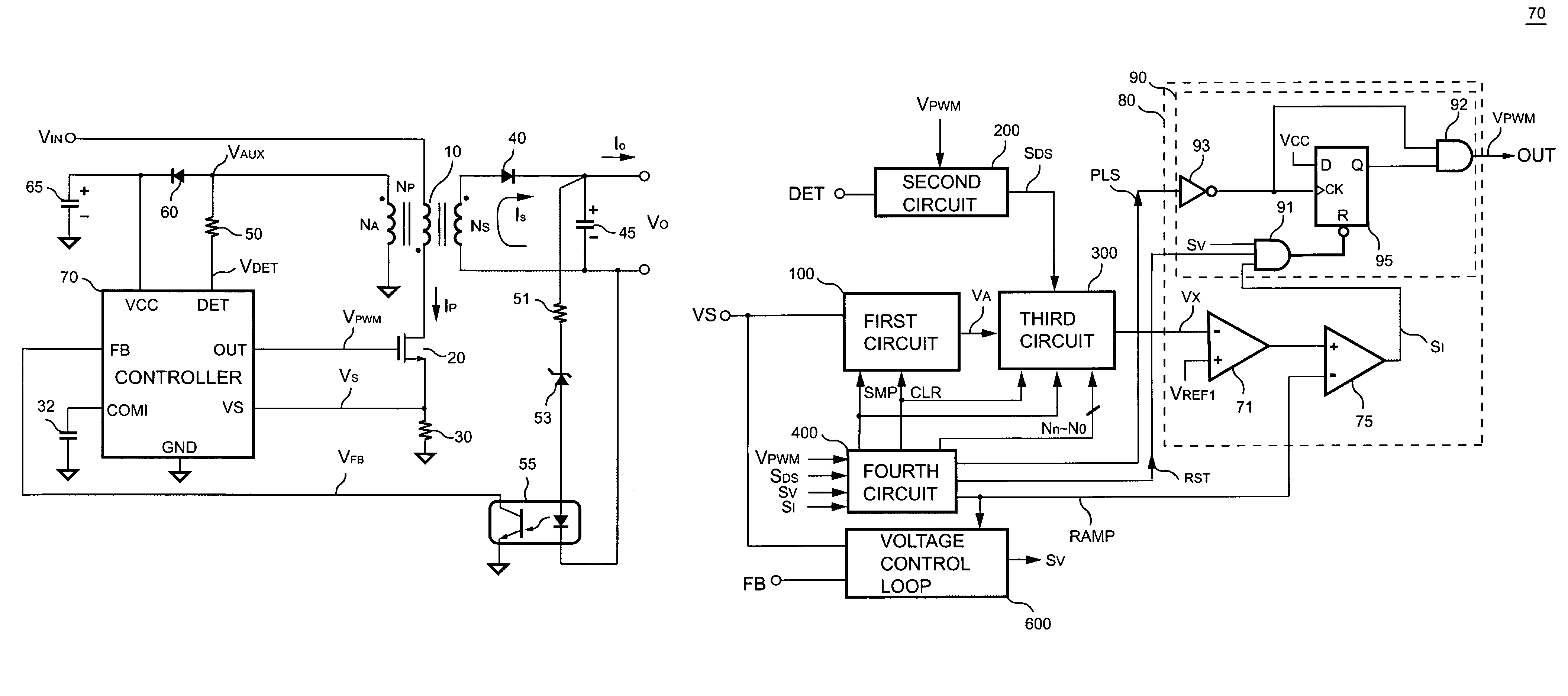
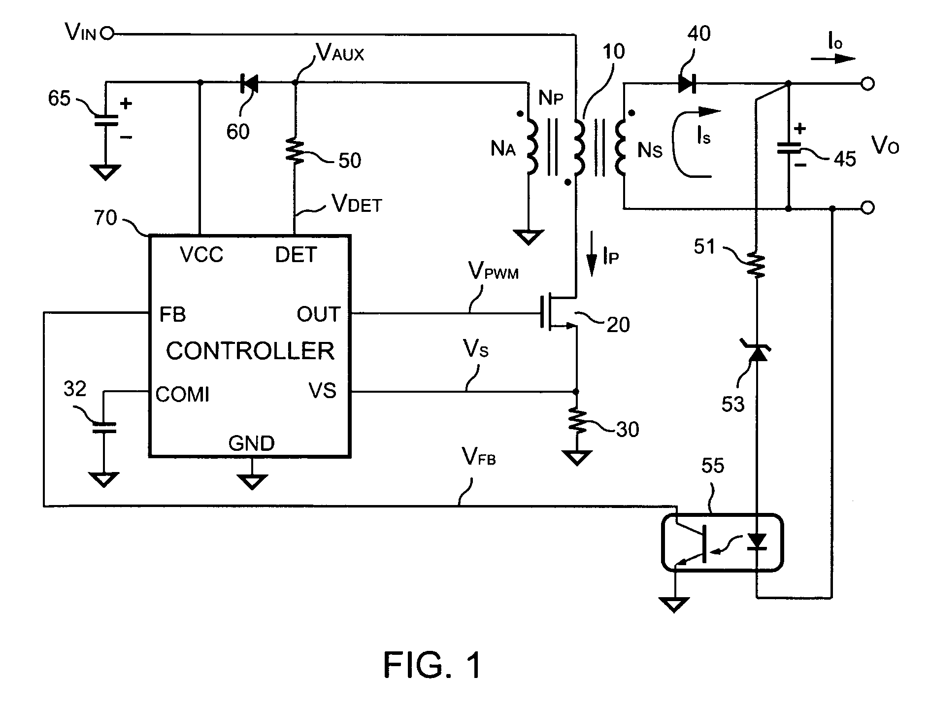
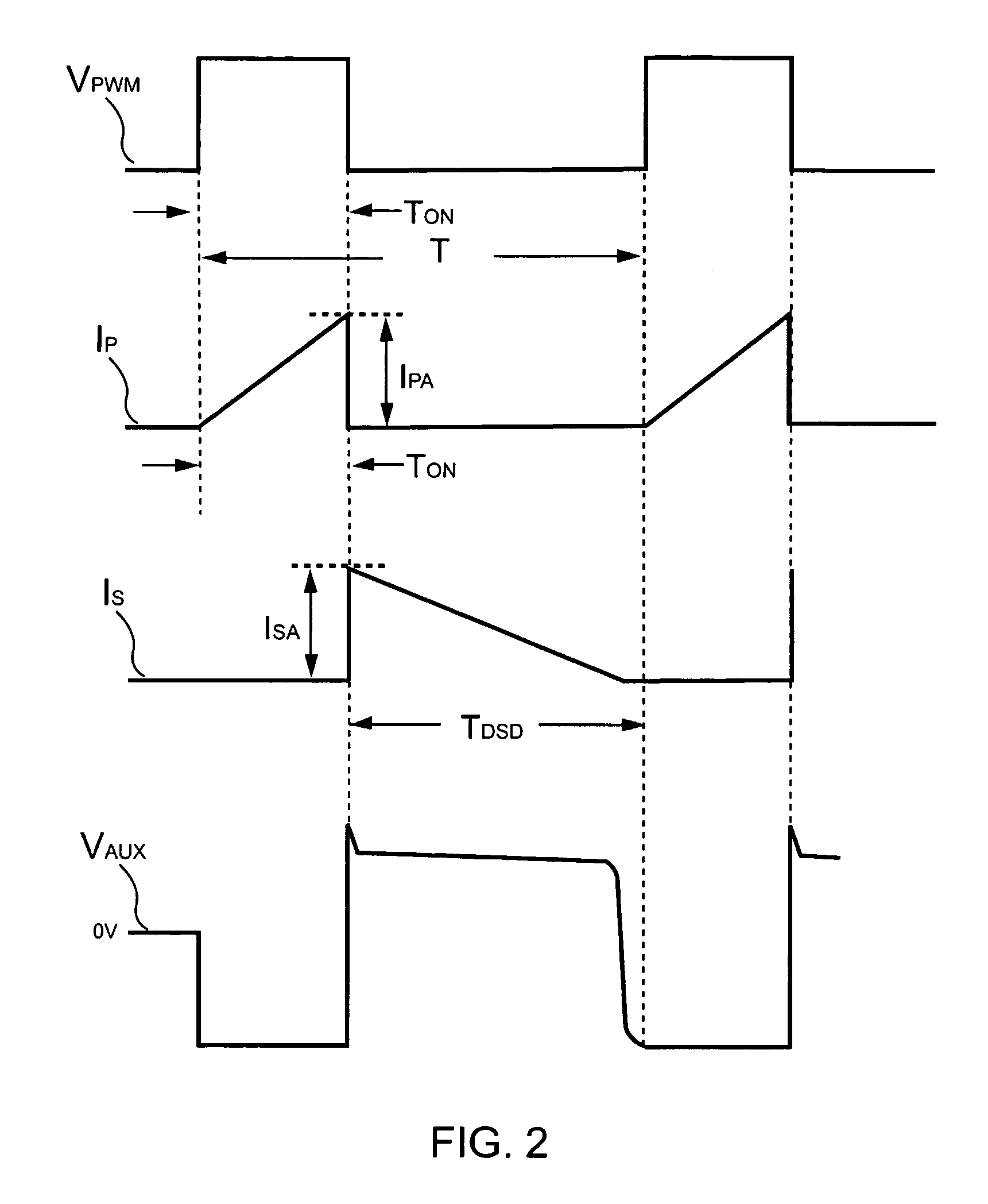
[0020]Referring to FIG. 1, a resonant power converter according to one embodiment of the present invention is illustrated. The resonant power converter comprises a transformer 10 having an auxiliary winding NA, a primary winding NP and a secondary winding NS. In order to regulate the output voltage VO and the output current IO of the power converter, a controller 70 generates a switching signal VPWM to switch the transformer 10 through a power transistor 20. Referring to FIG. 2, it illustrates waveforms of the resonant power converter in FIG. 1. A primary side switching current IP is generated as the switching signal VPWM becomes a high-level. A peak value IPA of the primary side switching current IP is given by,

[0021]IPA=VINLP×TON(1)

where VIN is an input voltage applied to the transformer 10, Lp is the inductance of the primary winding NP of the transformer 10, TON is an on-time of the switching signal VPWM.

[0022]Once the switching signal VPWM drops to a low-level, the stored energ...


PUM


Abstract

A controller controls the output current by measuring and controlling the switching current of the power converter. A first circuit generates a first signal in accordance with the switching current. A second circuit detects a discharge-time of the transformer. A third circuit generates a third signal by integrating the first signal with the discharge-time. The time constant of the third circuit is programmed and correlated with the switching period of the switching signal, therefore the third signal is proportional to the output current. A switching circuit generates a switching signal and controls the pulse width of the switching signal in accordance with the third signal and a reference voltage. Therefore, the output current of the power converter can be regulated.

Description

BACKGROUND OF THE INVENTION[0001]1. Field of the Invention[0002]The present invention relates to a power converter, and more particularly, to an output current controller of the resonant power converter.[0003]2. Description of Related Art[0004]A variety of power converters have been widely used to provide regulated voltage and current. In order to precisely control the output current, traditionally a current detection circuit and output control circuit is equipped at the output of the power converter. However, a considerable power loss is normally consumed due to the output current detection circuit, particularly as the output current is high-level. Besides, this output control circuit takes a space of the PCB (print circuit board) and increases the cost of the power converter. Thus it is desirable to provide a controller that combines with the output control circuit of the power converter for the output current control. The switching current of the power converter is normally small...

Claims


Application Information

Patent Timeline
Patent Type & Authority Patents(United States)
IPC IPC(8): H02M3/335
CPCH02M3/33523Y02B70/1433H02M2001/0009H02M1/0009Y02B70/10
Inventor YANG, TA-YUNG
Owner SEMICON COMPONENTS IND LLC
Why Eureka
Try Eureka