System and method for driving light-emitting diodes (LEDs)

a technology of light-emitting diodes and display systems, which is applied in the direction of electric variable regulation, process and machine control, instruments, etc., can solve the problems of uhp arc lamps that consume a large amount of power and produce a lot of heat, leds are more expensive than uhp arc lamps, and uhp arc lamps consume a large amount of power and heat, so as to reduce power consumption and reduce heat dissipation requirements , the effect of efficien

Active Publication Date: 2007-02-15
TEXAS INSTR INC
View PDF7 Cites 81 Cited by
  • Summary
  • Abstract
  • Description
  • Claims
  • Application Information

AI Technical Summary

Benefits of technology

[0010] An advantage of a preferred embodiment of the present invention is that current source circuitry for the LEDs are operated with minimum heat dissipation requirements for a desired LED light output level. This therefore leads to a more efficient power supply, reduced power consumption, and increased useful life for the driver circuitry of the LEDs.
[0011] A further advantage of a preferred embodiment of the present invention is that it is possible to rapidly attenuate light output levels of the LEDs to a desired level so that it is possible to change light output levels between rapidly changing images being displayed by the display system, rather than slowly changing light output levels between multiple images. This can result in improved control of image quality as well as power consumption.

Problems solved by technology

Unfortunately, the UHP arc lamps consume a large amount of power and produce a lot of heat.
Furthermore, LEDs tend to have longer life than UHP arc lamps.
One disadvantage of the prior art is that LEDs can be more expensive than UHP arc lamps.
This can lead to more expensive and complex display systems as well as potentially decrease reliability.
A second disadvantage of the prior art is that in order to optimize the power consumption of the LEDs, as well as increase useful life and light output, LEDs cannot simply be turned on.
This can further result in a more expensive and complex display system.

Method used


Image

  • System and method for driving light-emitting diodes (LEDs)
  • System and method for driving light-emitting diodes (LEDs)
  • System and method for driving light-emitting diodes (LEDs)

Examples


Embodiment Construction

[0019] The making and using of the presently preferred embodiments are discussed in detail below. It should be appreciated, however, that the present invention provides many applicable inventive concepts that can be embodied in a wide variety of specific contexts. The specific embodiments discussed are merely illustrative of specific ways to make and use the invention, and do not limit the scope of the invention.

[0020] The present invention will be described with respect to preferred embodiments in a specific context, namely a display system using LEDs as light sources. The invention may also be applied, however, to other applications wherein there is a need to efficiently provide power to high light output LEDs that consume large amounts of current to optimize power consumption and maximize product life, such as light beacons, road warning markers, lights, and so forth.

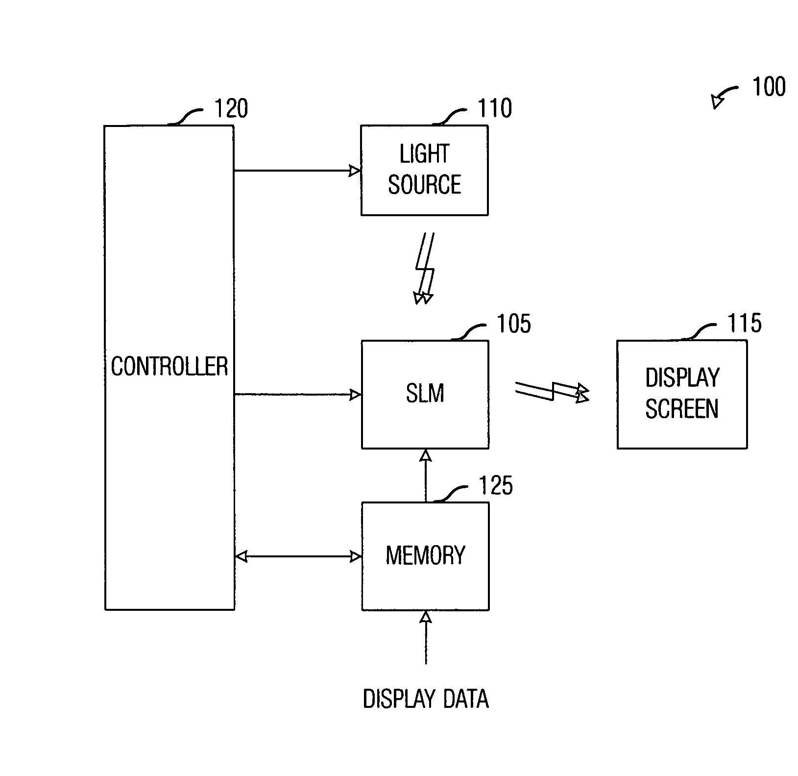
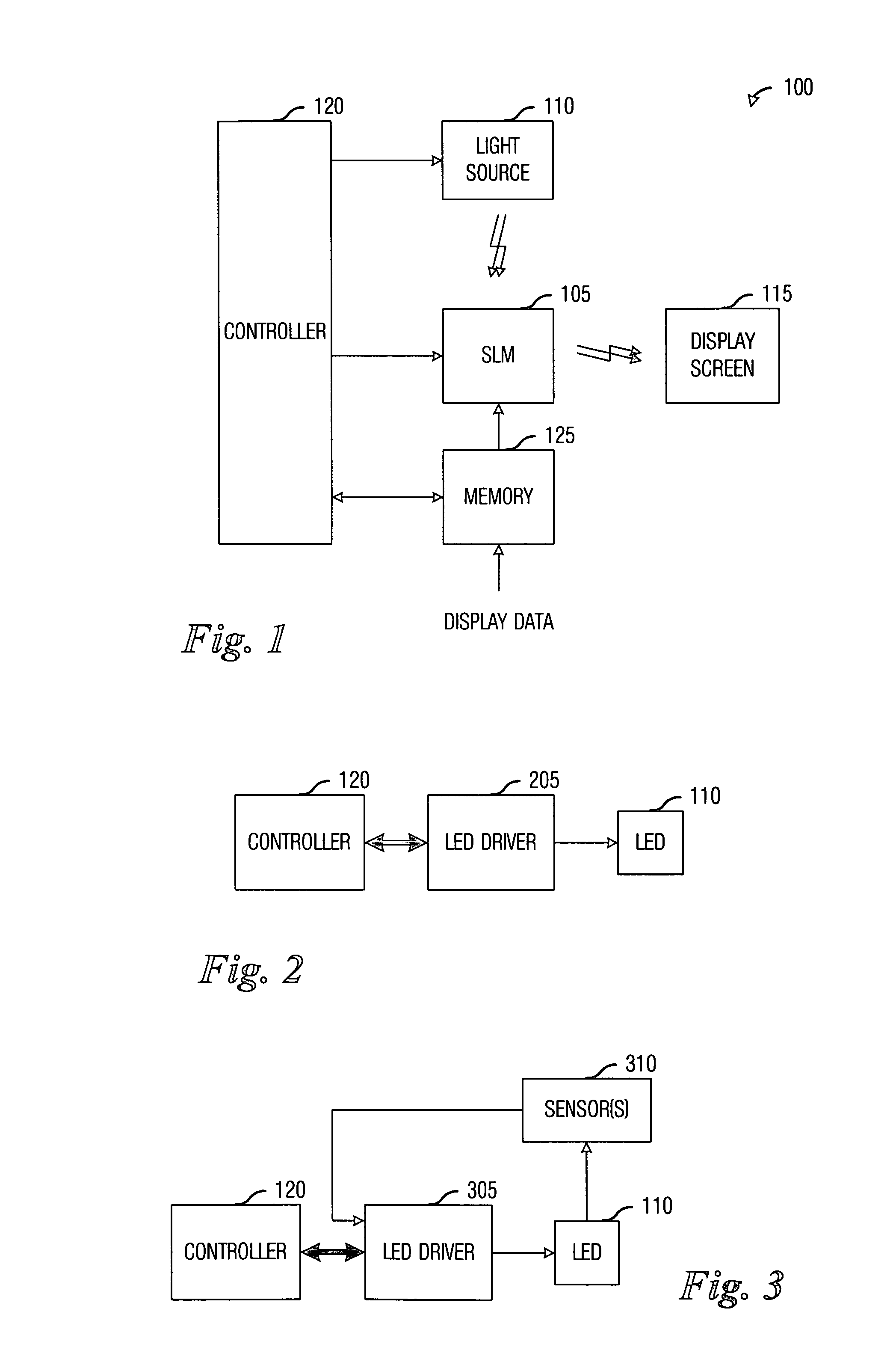
[0021] With reference now to FIG. 1, there is shown a diagram illustrating an exemplary display system 100, wher...


PUM


Abstract

System and method for improving efficiency in driving LEDs. A preferred embodiment comprises a switch current regulator coupled to a current control signal input, the switch current regulator to control an amount of current provided to the LED based upon a magnitude of a voltage on the current control signal input, a switching voltage regulator coupled to the switch current regulator and the LED, the switching voltage regulator to provide current to the LED, and a sensor coupled to the switch current regulator, the LED, and a signal feedback circuit, the sensor to measure status information regarding the switch current regulator and the LED and provides the information to a controller, wherein the status information can be used to adjust the current on the current control signal input.

Description

TECHNICAL FIELD [0001] The present invention relates generally to a system and method for display systems, and more particularly to a system and method for improving efficiency in driving LEDs. BACKGROUND [0002] Projection display systems have typically used ultra-high pressure (UHP) arc lamps to provide necessary light needed to project an image (or a sequence of images) on a display screen. The UHP arc lamps provide adequate brightness and have long life. Unfortunately, the UHP arc lamps consume a large amount of power and produce a lot of heat. [0003] Recently, LEDs have come to market that have been able to produce light at intensity levels rivaling that of the UHP arc lamps, especially when multiple LEDs are used in conjunction. LEDs have an advantage in that it is possible to use narrow-spectrum LEDs that produce light with specific colors, whereas the UHP arc lamps produce broad-spectrum light. Additionally, LEDs consume less power and produce less heat when compared to the U...

Claims


Application Information

Patent Timeline
Patent Type & Authority Applications(United States)
IPC IPC(8): G09G5/00H01L33/00H05B44/00
CPCH05B33/0851H05B33/0854H05B33/0812Y02B20/345Y02B20/343H05B45/18H05B45/14G09G5/00H05B45/10Y02B20/30
Inventor GARCIA, GETZEL GONZALEZMARSHALL, STEPHEN WESLEYPENN, STEVEN MONROE
Owner TEXAS INSTR INC
Why Eureka
Try Eureka