Photothermal resonance

a photothermal resonance and mechanical resonance technology, applied in the direction of material solids analysis using sonic/ultrasonic/infrasonic waves, instruments, etc., can solve the problems of thermomechanical noise, external vibration, and inability to obtain good specificity, etc., to achieve the effect of increasing the reliability of measurements

Inactive Publication Date: 2015-10-15
DANMARKS TEKNISKE UNIV
View PDF1 Cites 1 Cited by
  • Summary
  • Abstract
  • Description
  • Claims
  • Application Information

AI Technical Summary

Benefits of technology

[0028]Advantageously the apparatus may comprise a temperature regulating device for maintaining a constant ambient temperature at the mec

Problems solved by technology

Micro and nano-electromechanical resonators have offered a range of highly sensitive mass sensors, but obtaining good specificity is generally challenging.
Such gravimetric sensors lack intrin

Method used


Image

  • Photothermal resonance
  • Photothermal resonance
  • Photothermal resonance

Examples


Embodiment Construction

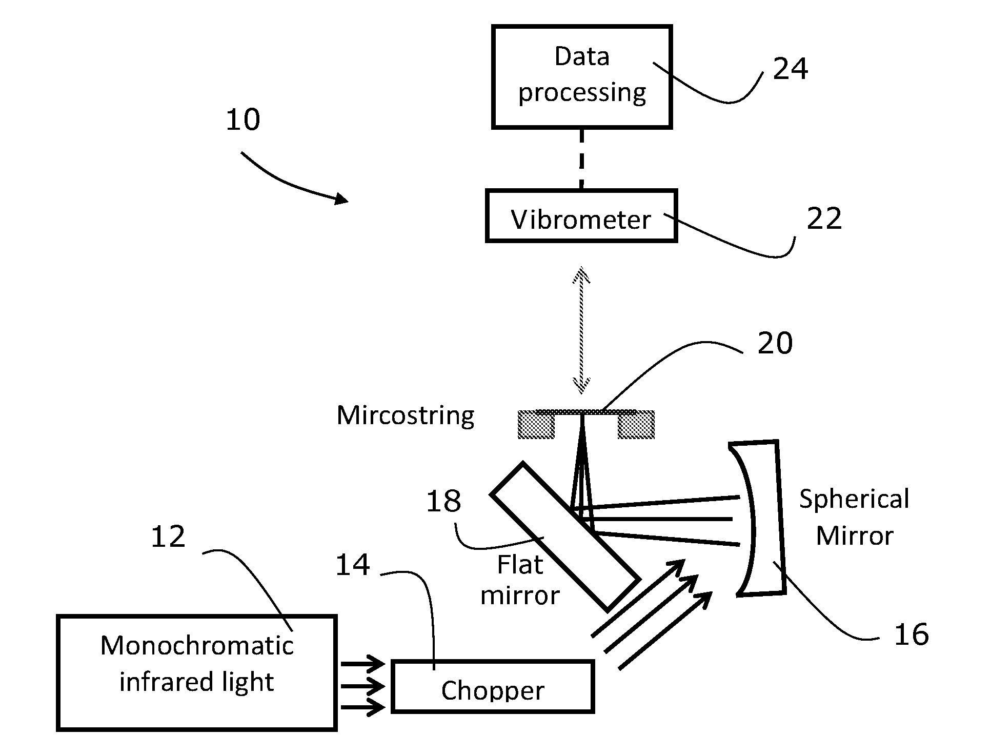
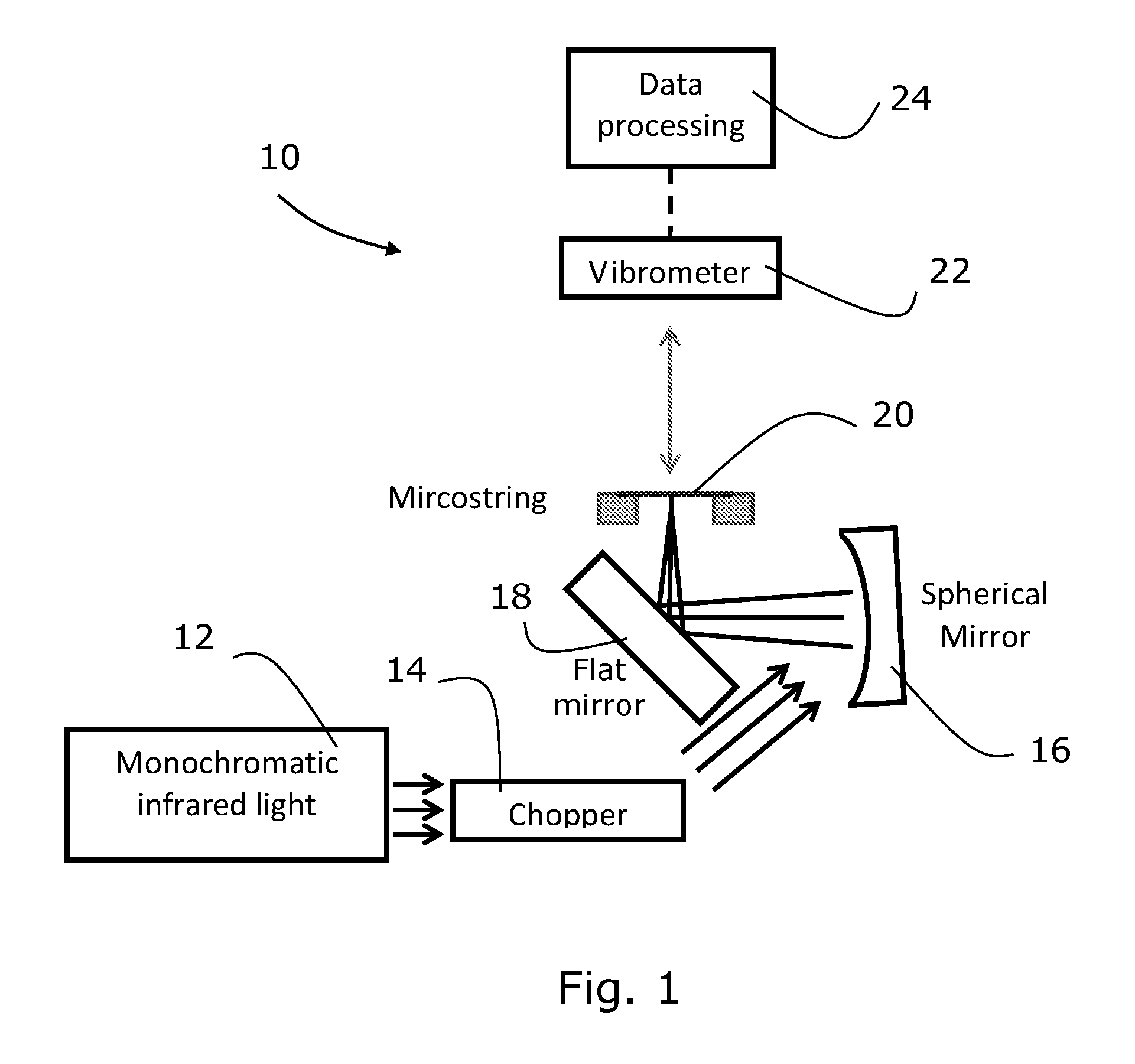
[0044]The photothermal resonance spectroscopy for airborne nanoparticles may be investigated by means of low stress silicon-rich silicon nitride as shown in FIG. 1.

[0045]FIG. 1 schematically illustrates a system 10 having a light source 12. The light source is here a monochromatic infrared light source. The light from the light source 12 is passed through a chopper 14. The chopper 14 chops the light signal at 1 Hz. In this embodiment the light source 12 sweeps the wavelength between 2.5 and 14.5 micrometer.

[0046]From the chopper 14 the light signal travels via a spherical mirror 16 and a flat mirror 18 so as to be focused on a microstring 20. Resonant micro and nano strings are of interest for sensor applications due to their extraordinary high quality factors and low mass. In the present specification the terms string and microstring are used interchangeably.

[0047]The microstring 20 is made from silicon nitride strings that have a thickness of 185 nm. The microstring 20 may in some...


PUM


Abstract

The present invention relates to a method for detecting photo-thermal absorbance of a material utilising a mechanically temperature sensitive resonator (20) and a sample being arrange in thermal communication with the temperature sensitive resonator. The present invention further relates to an apparatus for detecting photo-thermal absorbance of a sample.

Description

FIELD OF THE INVENTION[0001]The present invention relates to a method and apparatus for performing photo thermal mechanical resonance absorbance spectroscopy utilising shift in resonance frequency.BACKGROUND OF THE INVENTION[0002]From U.S. Pat. No. 5,923,421 a chemical detector is known. The detector comprises: an array of sensing elements, each having a characteristic physical parameter and a coating exhibiting a preferential adsorption of a chemical to be sensed.[0003]Further DE 38 18 888 discloses a method and a device specified for the detection of radiation absorptions of a substance by means of the detection of absorption-conditioned temperature changes of the substance.[0004]When monitoring for particles or compounds there is always a need for an improved method and system.[0005]Hence, an improved system for determining a characteristic of a material would be advantageous, and in particular a more efficient and / or reliable method for enabling determination of a compound or pa...

Claims


Application Information

Patent Timeline
IPC IPC(8): G01N21/39G01N29/24G01N21/17
CPCG01N21/39G01N21/1702G01N2291/014G01N2201/06113G01N29/2418G01N29/022G01N29/036G01N2291/0256G01N2291/0427
Inventor YAMADA, SHOKOSCHMID, SILVANBOISEN, ANJALARSEN, TOM
Owner DANMARKS TEKNISKE UNIV
Why Eureka
Try Eureka