Battery charger

a battery charger and battery technology, applied in the field of battery chargers, can solve the problems of shortened battery life, high heat generation while being charged, deterioration of the electrodes and separators of the cells within the battery,

Inactive Publication Date: 2001-02-20
MAKITA CORP
View PDF8 Cites 87 Cited by
  • Summary
  • Abstract
  • Description
  • Claims
  • Application Information

AI Technical Summary

Benefits of technology

The battery charger employs a map in which an allowable current value is mapped based on a battery temperature and a battery temperature rise value, with which a battery can be charged while battery temperature rise is being suppressed, and controls a charging current value. That is, by retrieving the map based on the battery temperature and the temperature rise value, an allowable current value, with which a battery can be charged while battery temperature rise is being suppressed, is obtained and the battery is charged with the allowable current value. Due to this, it is possible to charge a nickel metal hydride battery, in a short time which temperature tends to rise during charge, without causing deterioration due to temperature rise. In this case, if charge state determining means determines that a battery state is not in a final charging period, allowable current value retrieving means obtains a relatively high allowable value. That is, before the final charging period, battery charge is completed in a short time by applying high current without switching current values for adjustment purposes.
The battery charger employs a map in which an allowable current value is mapped and controls a charging current value, with which a battery can be charged while battery temperature rise is being suppressed. That is, by retrieving the map based on the battery temperature and the battery rise value, an allowable current value with which a battery can be charged while battery temperature rise is being suppressed is obtained and the battery is charged with the allowable current value. Due to this, it is possible to charge a nickel metal hydride battery in a short time, which temperature tends to rise during charge, without causing deterioration due to temperature rise. In this case, it is determined whether a battery status is before or in a final charging state based on the change of battery voltage and allowable current according to the battery charged state which is obtained from the map. Thus, it is possible to conduct optimum charging current control according to the battery charged status.

Problems solved by technology

Although the nickel metal hydride battery can increase a capacity compared to a nickel cadmium battery, it generates high heat while being charged.
If the temperature of the battery becomes high by the generated heat, the electrodes and separator of the cell within the battery deteriorate and battery life is shortened.
Due to this, it is impossible to quickly charge the nickel metal hydride battery with high current as done for the nickel cadmium battery stated above.
However, if charging a battery by using this method, the switching of current values occurs frequently even in the earlier and medium periods of battery charge and charging time is disadvantageously lengthened.
In that case, however, as temperature resolution increases, cost increases.

Method used


Image

  • Battery charger
  • Battery charger
  • Battery charger

Examples


first embodiment

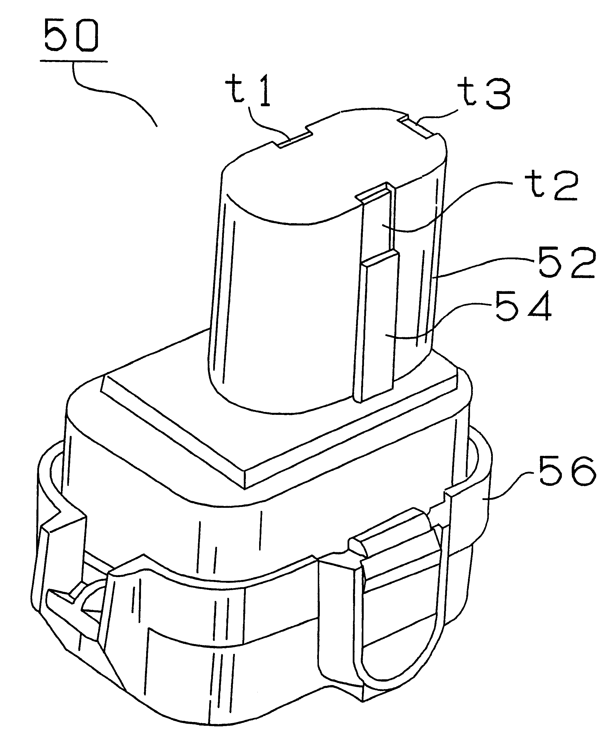
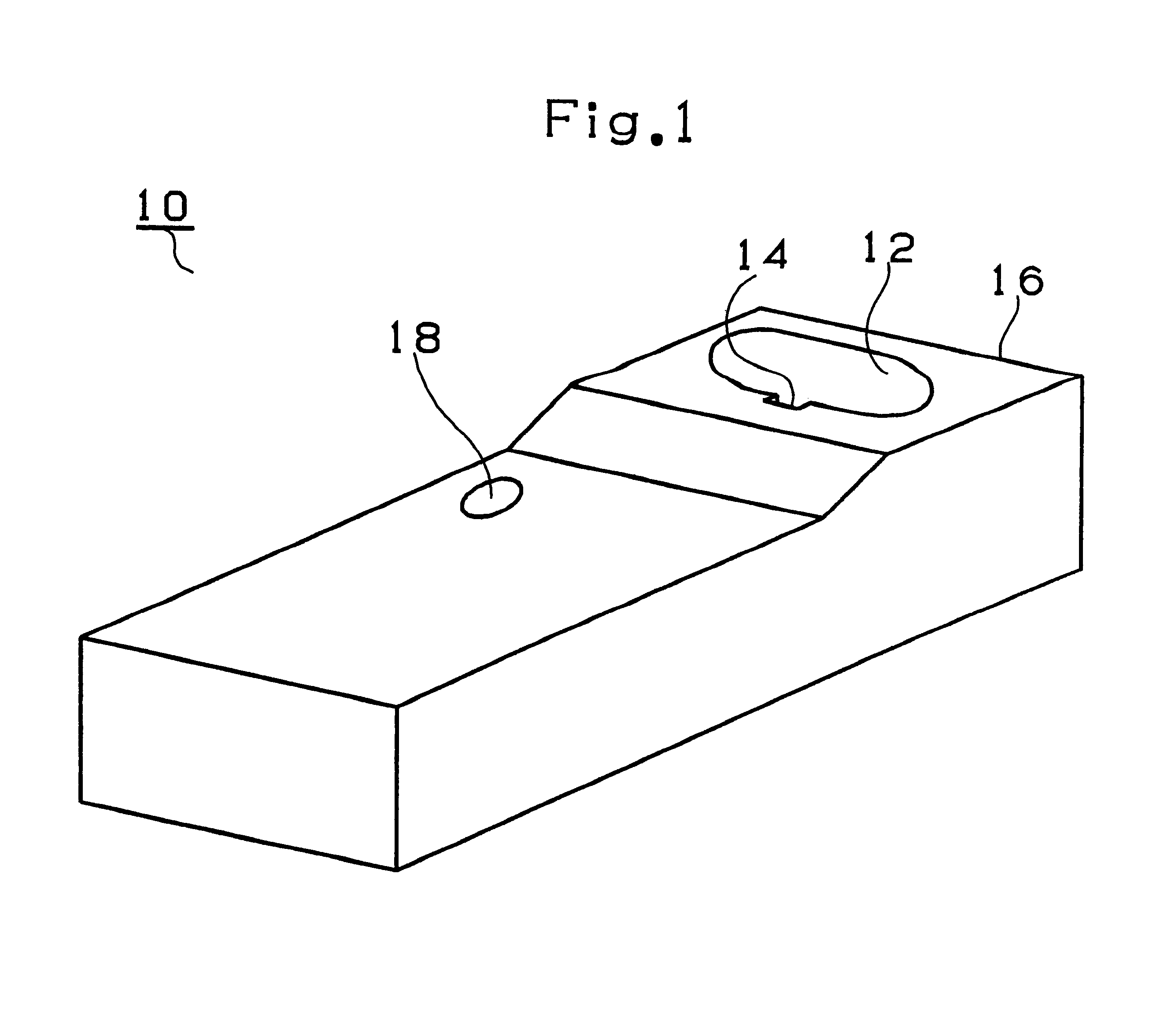
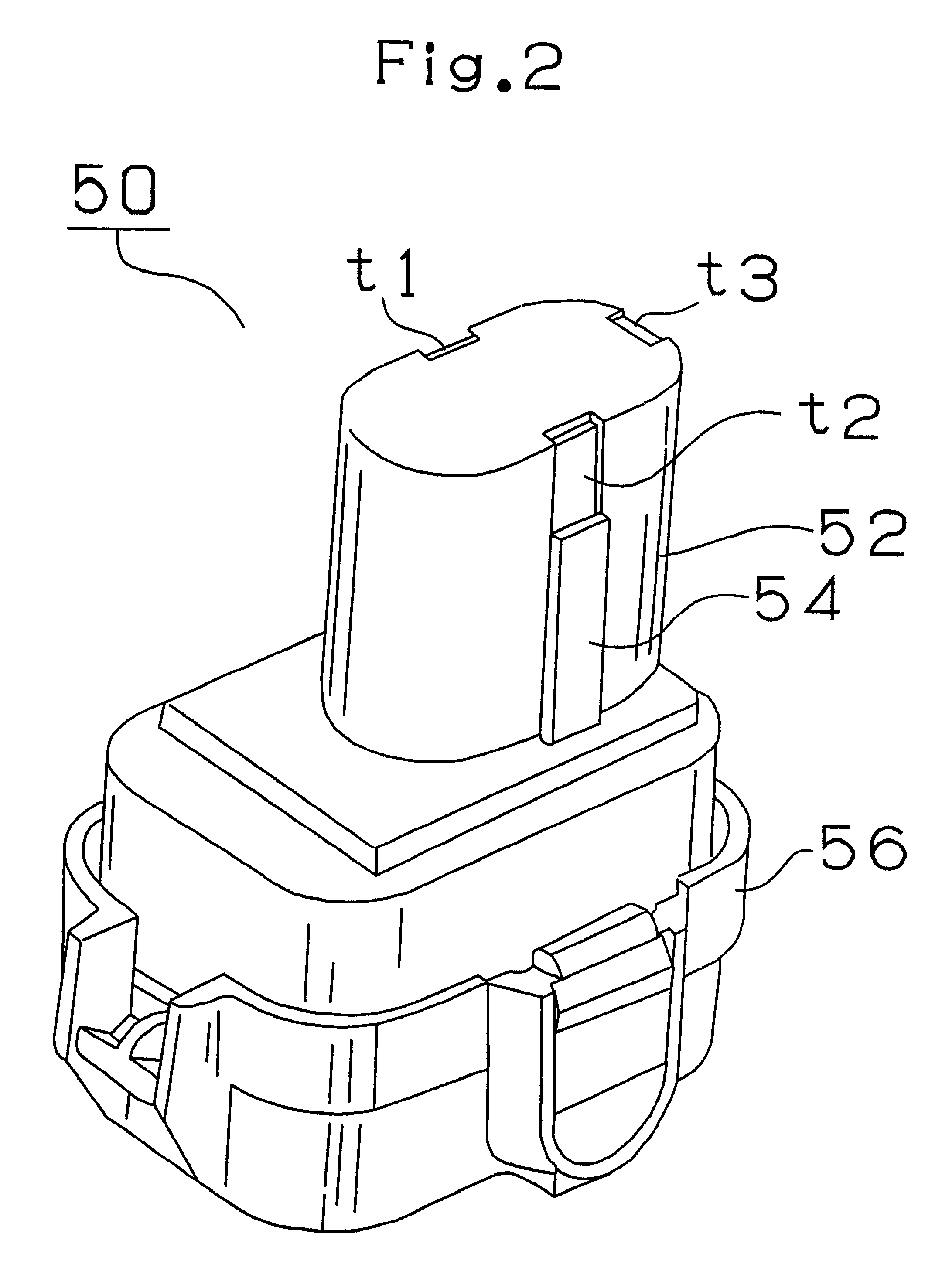
FIG. 1 shows a battery charger 10 in the first embodiment, FIG. 2 shows a battery pack 50 (for a nickel metal hydride battery) and FIG. 3 shows a battery drill 70 driven by the battery pack 50.

As shown in FIG. 2, the battery pack 50 containing a nickel metal hydride battery consists of a generally cylindrical fitted part 52 and a generally prismatic base 56. A key-shaped key part 54 is formed on the side of the fitted part 52 and the first input terminal t1 connected to the positive electrode of the battery, the second input terminal t2 connected to the negative electrode thereof and the third terminal t3 connected to a temperature detecting sensor consisting of a thermistor are arranged on the upper portion of the fitted part 52. The battery pack 50 is adapted to different voltages, i.e., 14.4 V, 12 V and 9.6 V, based on the difference in the number of battery cells contained therein.

As shown in FIG. 1, the battery charger 10 charging the battery packs 50 is provided with a fitting...

third embodiment

The processings by the battery charger in the third embodiment will be described with reference to FIGS. 13 and 14.

FIG. 13 shows the first half of the processings in the third embodiment. The processings in steps 12 to 50 in FIG. 13 are the same as those in the first embodiment described above with reference to FIGS. 8 and 9. Therefore, no description will be given thereto.

FIG. 14 shows the second half of the processings for completing battery charge in the third embodiment. In a step S136, it is determined whether a change in voltage dV / dt is less than Vc (a voltage decrease value at the time of full charge) set in the step S28, i.e., whether the battery state is in the final charging period. If it is determined that the battery state is in the final charging period (`Yes` in the step S136), the counter for determining charge completion is incremented by 1 (in a step S138). If it is determined that the battery is not in the final charging period from the change in voltage dV / dt (`N...

fourth embodiment

The processings by the battery charger in the fourth embodiment will be described with reference to FIG. 15.

FIG. 15 shows the second half of the processings in the fourth embodiment. Since the first half of the processings in the fourth embodiment are the same as that in the third embodiment described above with reference to FIG. 13, no description will be given thereto.

First, it is determined whether the retrieval target region based on battery temperature belongs to the final charging period region (1) shown in FIG. 5 in a step S232. If it belongs to the final charging period region (1) (`In` in the step S232), the counter is incremented by 3 (in a step S234). If it does not belong to the final charging region (1) (`Out` in the step S232), it is then determined whether the target region belongs to the final charging period region (2) shown in FIG. 5 (in a step S236). If it belongs to the final charging period region (2) (`In` in the step S236), the counter is incremented by 6 (in ...


PUM

PropertyMeasurementUnit
voltagesaaaaaaaaaa
voltagesaaaaaaaaaa
voltagesaaaaaaaaaa

Abstract

A map is retrieved based on a battery temperature and a temperature rise value (in a step S40) and an allowable current value, with which a battery can be charged while battery temperature rise is being suppressed, is obtained and the battery is charged with the allowable current value (in a step S42). By doing so, it is possible to charge a nickel metal hydride battery in a short time without causing deterioration due to temperature rise. If it is determined that a battery state is not in a final charging period from the change of battery voltage ("Yes' in a step S30), a change in temperature is corrected (in a step S34) and a relatively high allowable current value is thereby obtained from the map (in a step S40). That is, before the final charging period, battery charge can be completed in a short time by applying high current without switching current values for adjustment purposes.

Description

1. Field of the InventionThe present invention relates to a battery charger suited or charging a battery, such as a nickel metal hydride battery, which emits high heat while being charged.2. Description of the Related ArtPresently, a chargeable battery which can be repeatedly used for the power supply of, for example, a power tool is used. A nickel cadmium battery is popular as a battery for the power tool, and a battery charger for quickly charging a battery by applying high current to the battery is used. Specifically, the battery is quickly charged in about 20 minutes and a power tool can be continuously used by changing a battery to a battery which has been charged.The inventor of the present invention studied improving the performance of a power tool by using a nickel metal hydride battery as a battery therefore. Although the nickel metal hydride battery can increase a capacity compared to a nickel cadmium battery, it generates high heat while being charged. If the temperature ...

Claims


Application Information

Patent Timeline
Patent Type & Authority Patents(United States)
IPC IPC(8): H02J7/00H02J7/10H01M10/44
CPCH02J7/008H02J7/007184
Inventor SAKAKIBARA, KAZUYUKI
Owner MAKITA CORP
Why Eureka
Try Eureka