Method and apparatus to switch operating modes in a PFM converter

a technology of operating mode and pfm converter, which is applied in the direction of power conversion system, dc-dc conversion, instruments, etc., can solve the problem that both modes of operation can promote inefficiency

Inactive Publication Date: 2006-09-05
MICROSEMI
View PDF35 Cites 88 Cited by
  • Summary
  • Abstract
  • Description
  • Claims
  • Application Information

AI Technical Summary

Benefits of technology

[0020]These and other objects and advantages of the present invention will become more fully apparent from the following description taken in conjunction with the accompanying drawings. For purpose of summarizing the invention, certain aspects, advantages and novel features of the invention have been described herein. It is to be understood that not necessarily all such advantages may be achieved in accordance with any particular embodiment of the invention. Thus, the invention may be embodied or carried out in a manner that achieves or optimizes one advantage or group of advantages as taught herein without necessarily achieving other advantages as may be taught or suggested herein.

Problems solved by technology

Both modes of operation can promote inefficiency (e.g., switching loss or conduction loss) as load current changes.

Method used


Image

  • Method and apparatus to switch operating modes in a PFM converter
  • Method and apparatus to switch operating modes in a PFM converter
  • Method and apparatus to switch operating modes in a PFM converter

Examples


Embodiment Construction

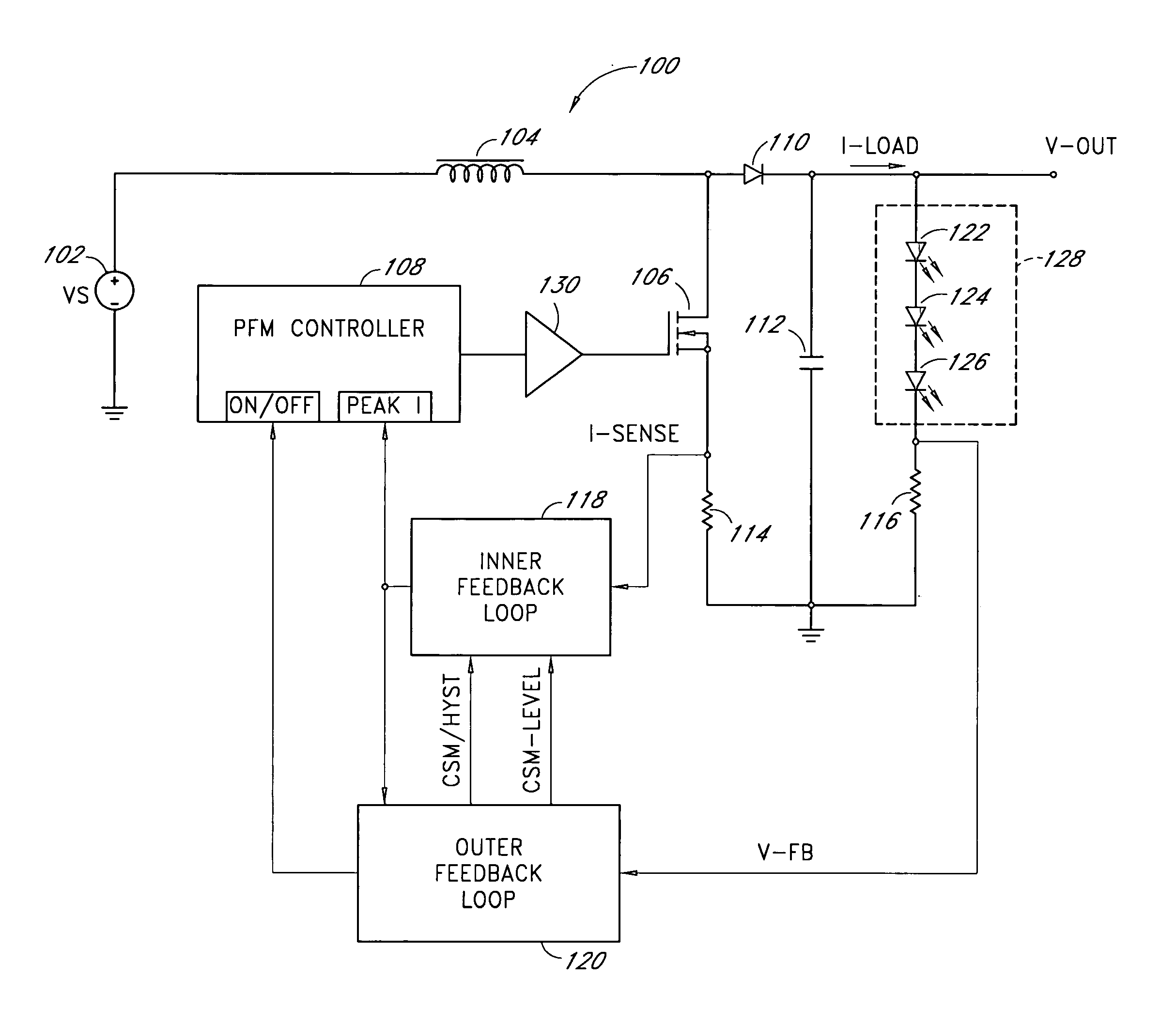
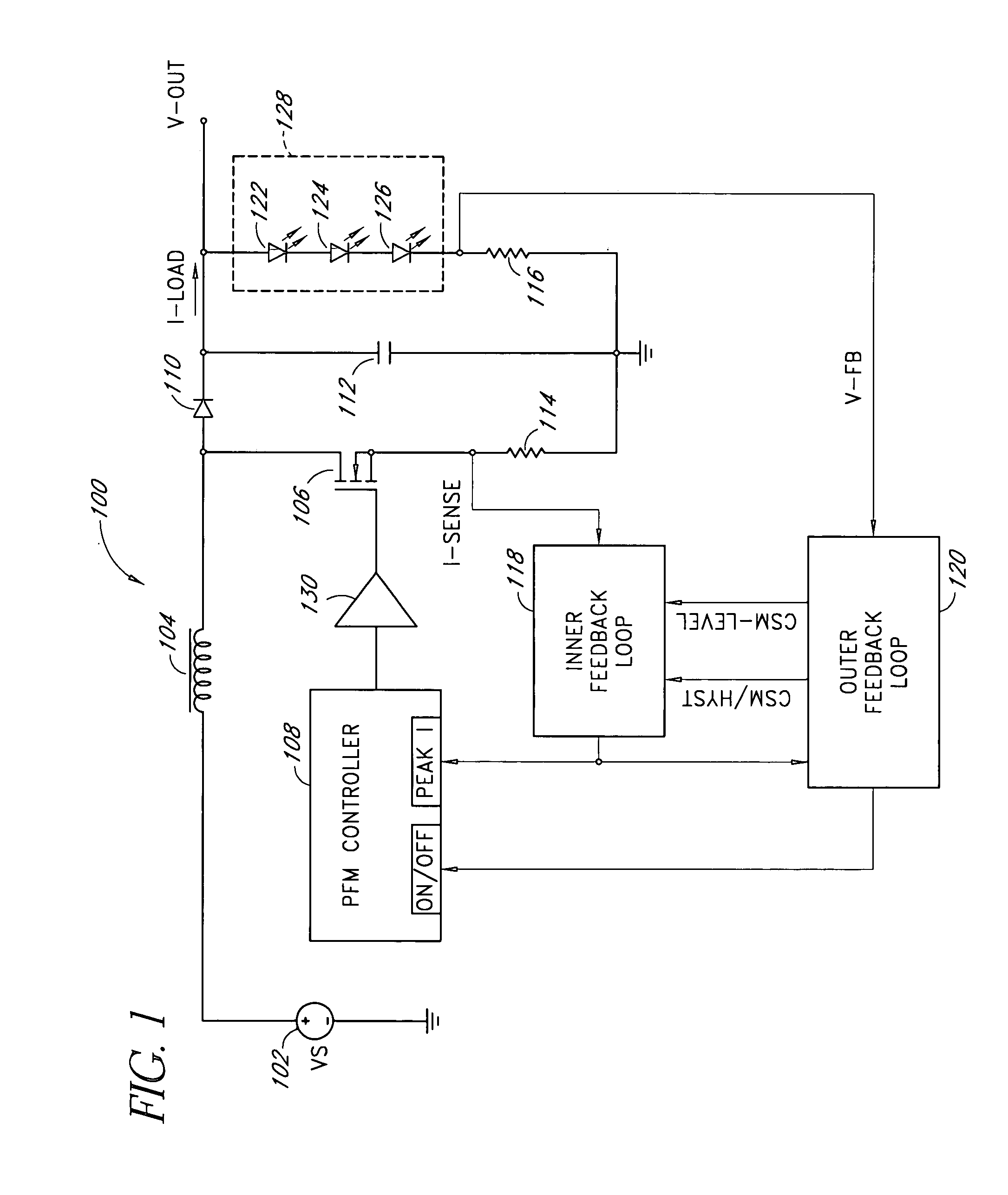
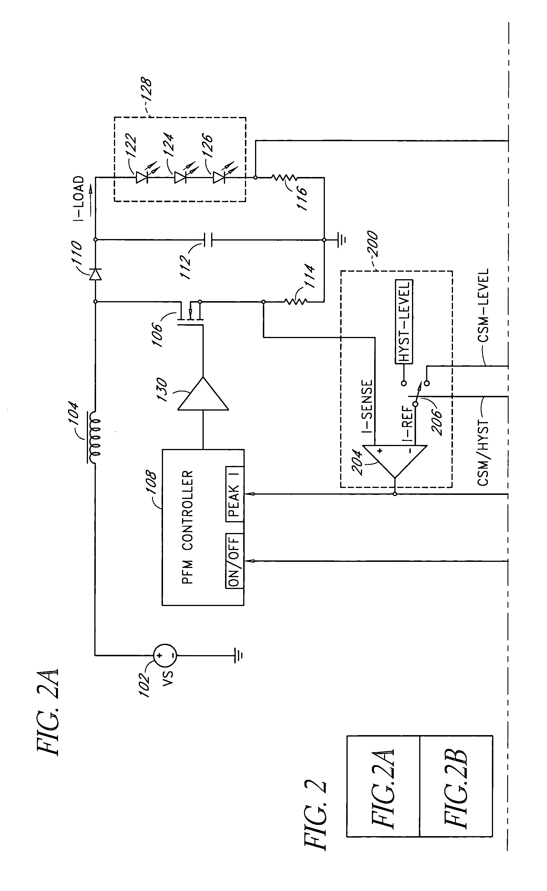
[0024]Embodiments of the present invention will be described hereinafter with reference to the drawings. FIG. 1 illustrates a simplified schematic diagram of one embodiment of a dual-mode boost converter 100. The dual-mode boost converter 100 accepts a direct current (DC) input voltage (VS) 102 and produces a DC output voltage (V-OUT) which can be greater than the input voltage 102. The output voltage can be used to power a load 128, e.g., three light emitting diodes (LEDs) 122, 124, 126 connected in series. The dual-mode boost converter 100 can adjust the brightness of the LEDs 122, 124, 126 by varying the power (or load current) provided to the load 128. In some applications, the load current (I-LOAD) varies over a wide range to accommodate a wide range of ambient lighting conditions.

[0025]The dual-mode boost converter 100 includes an input inductor 104, a switch 106, a rectifying diode 110, a filter capacitor 112, and sense resistors 114, 116. In one embodiment, the switch 106 is...


PUM


Abstract

A dual-mode pulse frequency modulation boost converter operates in a hysteretic mode during light load currents to regulate an output voltage using a substantially fixed peak switching current and operates in a continuous mode during heavy load currents to regulate the output voltage using a variable peak switching current. The boost converter senses load power to automatically switch between the hysteretic mode and the continuous mode.

Description

CLAIM FOR PRIORITY[0001]This application claims the benefit of priority under 35 U.S.C. § 119(e) of U.S. Provisional Application No. 60 / 441,702, filed on Jan. 21, 2003, and entitled DUAL-MODE PFM BOOST CONVERTER, the entirety of which is incorporated herein by reference.BACKGROUND OF THE INVENTION[0002]1. Field of the Invention[0003]The present invention relates generally to power conversion circuits and more particularly to a boost converter that uses two pulse frequency modulation (PFM) operating modes for efficiency.[0004]2. Description of the Related Art[0005]Inductor based boost mode light emitting diode (LED) drivers typically include pulse width modulation (PWM) converters that operate at a fixed frequency. A PWM converter uses an oscillator to generate the fixed (or PWM reference) frequency and varies the switching duty cycle applied to a semiconductor switch to regulate an output voltage. The PWM converter can operate in a voltage mode or a current mode. In a current mode P...

Claims


Application Information

Patent Timeline
Patent Type & Authority Patents(United States)
IPC IPC(8): G05F1/40
CPCH02M3/157
Inventor FERGUSON, BRUCE R.
Owner MICROSEMI
Why Eureka
Try Eureka