Paint tray caddy for extension ladders and method of use thereof

a technology for painting trays and ladders, which is applied in the field of painting trays caddies, can solve the problems of compromising safety, not without disadvantages, and not providing a work area or storage area for the person on the ladder

Inactive Publication Date: 2011-10-11
CULL GERALD R
View PDF23 Cites 13 Cited by
  • Summary
  • Abstract
  • Description
  • Claims
  • Application Information

AI Technical Summary

Benefits of technology

[0015]The removable attaching mechanism further includes a rectilinear second stop member integrally attached to the respective bottom surfaces of the upper arms. Such a second stop member has a longitudinal length registered perpendicular to the respective longitudinal lengths of the upper arms, and the second stop member is located subjacent of the tubes and spaced from the first stop member. A first dowel rod has axially opposed and threaded proximal and distal ends respectively, and the proximal end of the first dowel rod is removably interfitted within a selected one of the plurality of tubes. The proximal end of the first dowel rod is threadably interfitted within an associated one of the openings of the locking plate when the first dowel rod is removably interfitted within the selected tube. The first and second stop members respectively provide an additional measure of safety when employing the apparatus by preventing an associated locking plate from prematurely and undesirably shifting position during operating conditions.
[0016]The removable attaching mechanism further includes a cylindrical adapter that has a threaded inner surface. Such an adapter has a diameter that is greater than a diameter of the first dowel rod, which is vital such that the distal end of the first dowel rod is threadably interfitted within the adapter. A second dowel rod has axially opposed and threaded proximal and distal ends respectively, and the proximal end of the second dowel rod is simultaneously and threadably interfitted within the adapter when the distal end of the first dowel rod is threadably interfitted within the adapter. The first and second dowel rods respectively are removably interfitted within a hollow cavity of a selected ladder rung of an existing ladder, which is necessary such that the first and second dowel rods respectively maintain the frame and the tray respectively in a stable position and spaced from the existing ladder during operating conditions. The adapter allows the user the choice of employing only the first dowel rod or the first dowel rod and the second dowel rod respectively based upon the size of the existing ladder that the apparatus is being attached to.
[0017]The removable attaching mechanism further includes an end cap attached to the distal end of the second dowel rod. Said end cap providing a lateral safety stopping mechanism to the second dowel rod so as to stop the second dowel rod from prematurely and undesirably disconnecting from the ladder rung during operating conditions.

Problems solved by technology

However, as handy as ladders are, they are not without their disadvantages.
Perhaps the biggest disadvantage is that they do not provide a work area or storage area for the person on the ladder.
This obviously compromises safety.
Additionally, the situation inevitably arises where the required tool, supply item or material is not on hand and, as a result, time and money are wasted in climbing back down the ladder, tracking the item down and then climbing back up the ladder.
Unfortunately, this prior art example is not suitable for holding odd shaped objects such as saws and drills.
Unfortunately, this prior art example interferes with a user's ability to safely and easily move up and down an existing ladder.
Unfortunately, this prior art example is not designed for holding odd shaped items and further also impedes the ability of a user to move up and down the ladder while the apparatus is attached thereto.
None of the prior art particularly describes a paint tray caddy employable with extension ladders for holding paint and working tools without interfering with the safety of a person standing on the ladder.

Method used


Image

  • Paint tray caddy for extension ladders and method of use thereof
  • Paint tray caddy for extension ladders and method of use thereof
  • Paint tray caddy for extension ladders and method of use thereof

Examples


Embodiment Construction

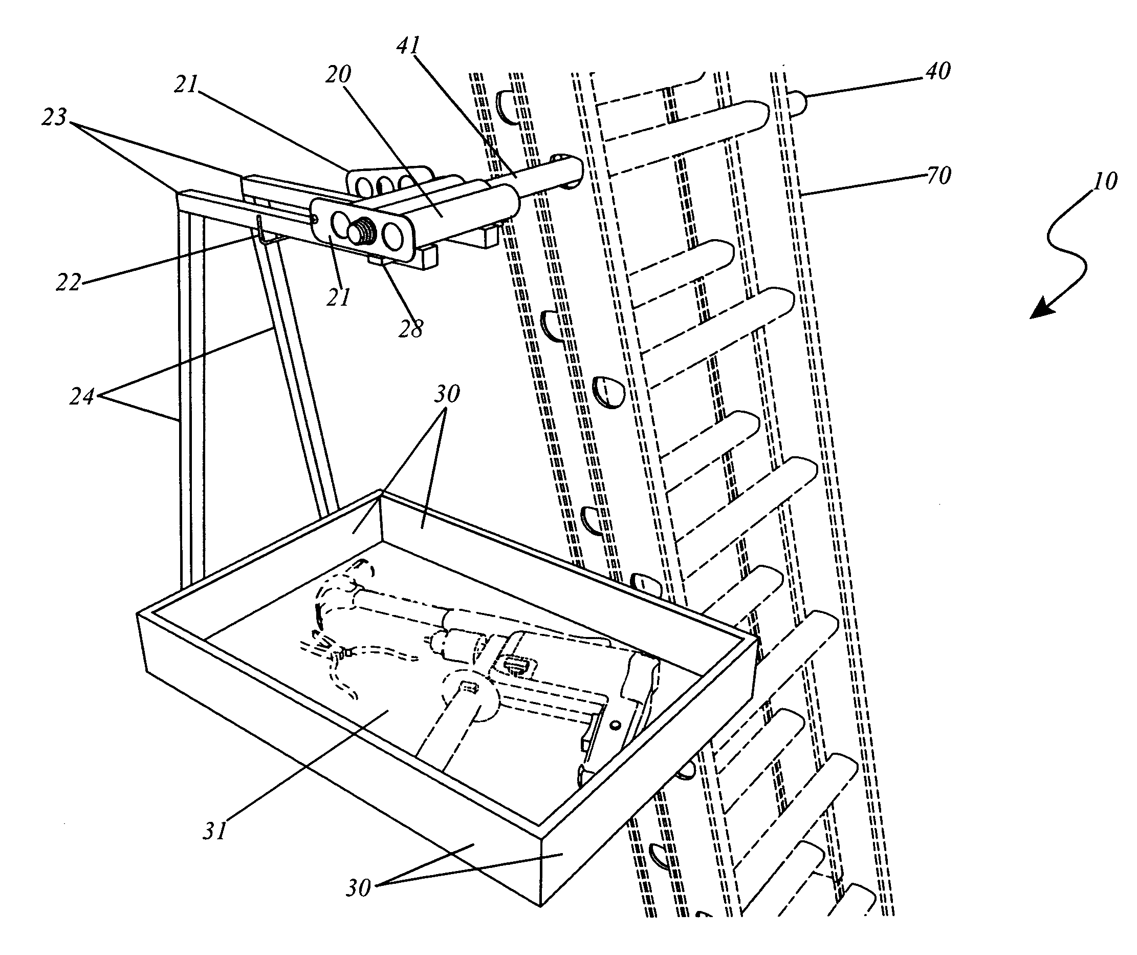
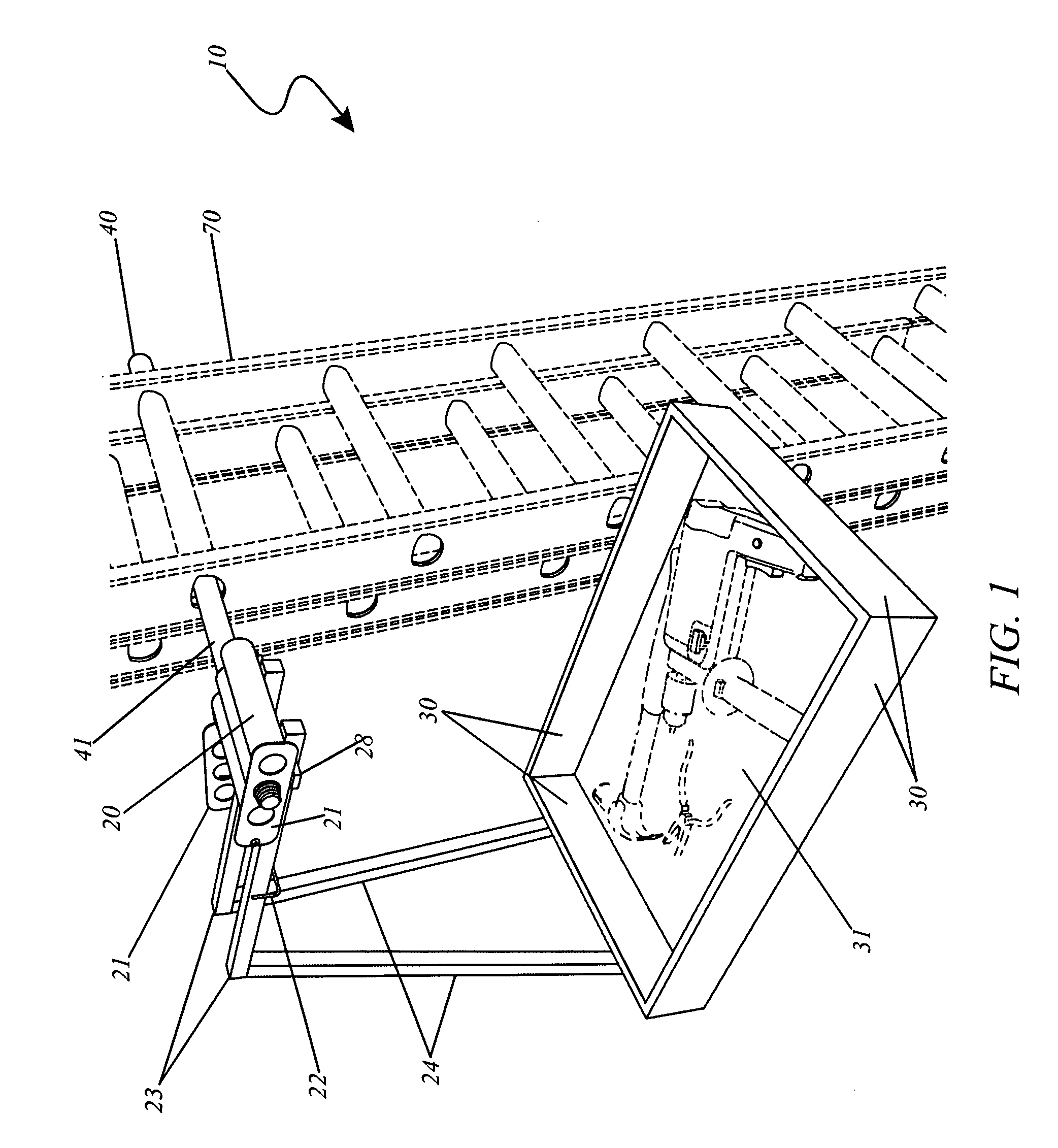
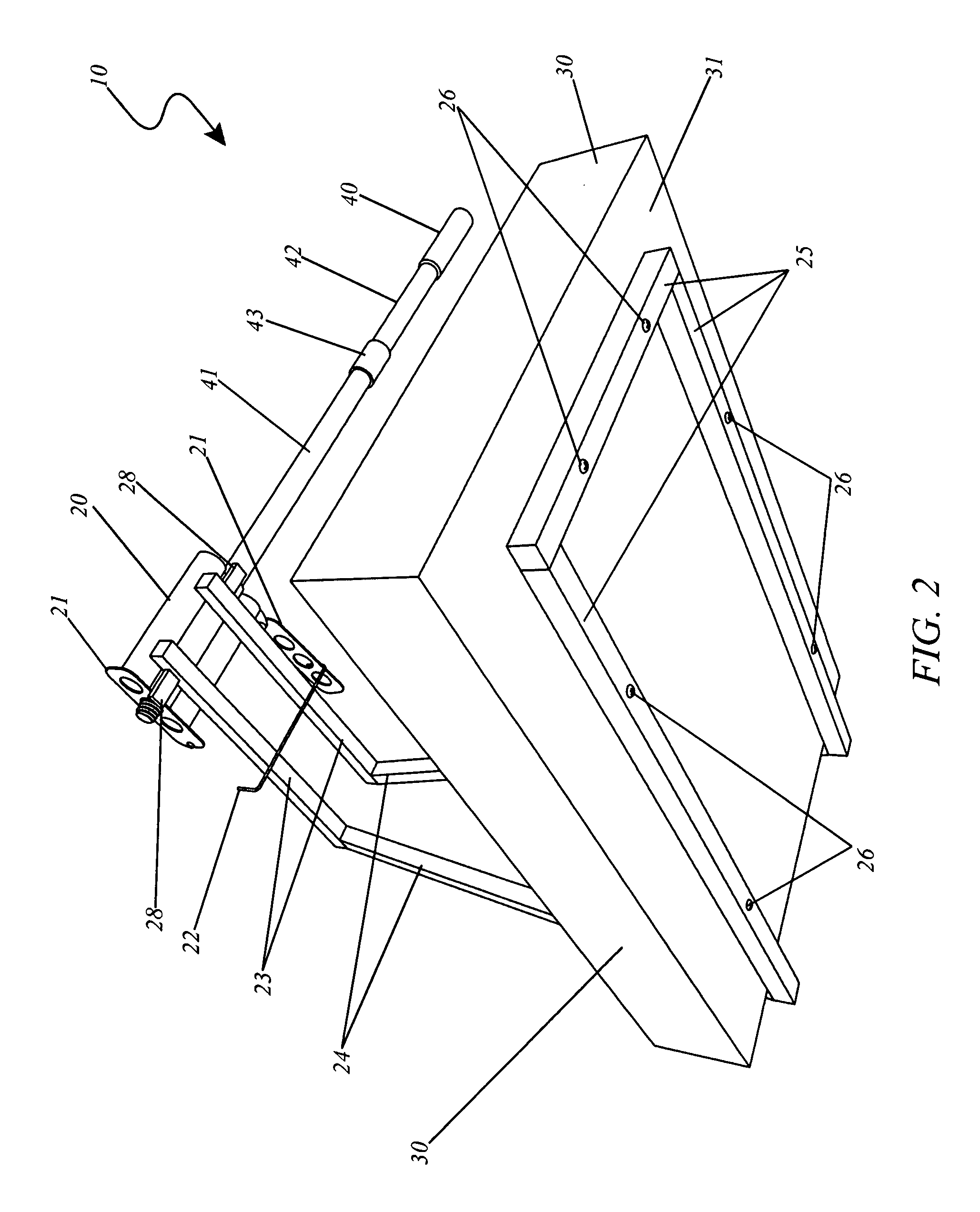
[0026]The best mode for carrying out the invention is presented in terms of its preferred embodiment, herein depicted within FIGS. 1 through 3. However, the invention is not limited to the described embodiment and a person skilled in the art will appreciate that many other embodiments of the invention are possible without deviating from the basic concept of the invention, and that any such work around will also fall under scope of this invention. It is envisioned that other styles and configurations of the present invention can be easily incorporated into the teachings of the present invention, and only one particular configuration shall be shown and described for purposes of clarity and disclosure and not by way of limitation of scope.

[0027]The terms “a” and “an” herein do not denote a limitation of quantity, but rather denote the presence of at least one of the referenced items.

[0028]The present invention describes an apparatus and method for a paint tray caddy for extension ladde...


PUM


Abstract

A caddy apparatus designed to hold paint, construction items, supplies, tools and other materials while on an extension ladder without interfering with the safety of the person standing on the ladder is herein disclosed. The apparatus uses a dimensioned dowel rod which is selectably placed through the hollow cavity of the ladder rungs and extends through to either side where it is used to support the apparatus. The apparatus comprises a “U”-shaped bracket, which is supported on the dowel rod in any one of three closely-spaced hanging tubes. The base of the bracket provides a large flat tray for use in holding materials while working on the extension ladder. The use of said caddy allows workers on extension ladders quick access to tools, supplies and materials in an efficient and safe manner.

Description

RELATED APPLICATIONS[0001]The present invention was first described in and claims the benefit of Disclosure Document No. 608,330, filed Nov. 2, 2006, the entire disclosures of which are incorporated herein by reference.FIELD OF THE INVENTION[0002]This invention relates to paint tray caddies and, more particularly, to a paint tray caddy employable with an extension ladder for holding paint and working tools without interfering with the safety of a person standing on the ladder.BACKGROUND OF THE INVENTION[0003]There is a seemingly endless list of activities performed at home, work, and in m any other environments that require the use of a ladder in order to allow its user to gain access to areas that otherwise would be inaccessible. However, as handy as ladders are, they are not without their disadvantages. Perhaps the biggest disadvantage is that they do not provide a work area or storage area for the person on the ladder. This requires the person to carry any tools or supplies neede...

Claims


Application Information

Patent Timeline
Patent Type & Authority Patents(United States)
IPC IPC(8): E06C7/14
CPCE06C7/143
Inventor CULL, GERALD R.
Owner CULL GERALD R
Why Eureka
Try Eureka