
Folding unit and method of folding corrugated cardboard sheet

Active Publication Date: 2011-10-11
EMBA HLDG AB
View PDF15 Cites 13 Cited by
  • Summary
  • Abstract
  • Description
  • Claims
  • Application Information

AI Technical Summary

Benefits of technology

[0012]The production in an inline machine is characterised by shorter and shorter series of box blanks. The changeover times of the machines will therefore have an increasing effect on the productivity of the machines. In modern inline machines, improved automatic systems are desired for setting the machines. The invention is an essential part in this development while at the same time it allows improved quality of the corrugated cardboard boxes by greater accuracy in folding. The setting of the folding movement was previously left to the experience and accuracy of the operator by many of the settings being manual. The automatic system now allows the machine to be set for an automatic folding movement depending on the size and geometry of the boxes.
[0013]An object of the present invention thus is to provide a folding unit for corrugated cardboard sheets in inline production of corrugated cardboard boxes, resulting in greater accuracy in folding of the corrugated cardboard sheets.
[0014]Another object of the invention is to provide a folding unit for corrugated cardboard sheets which are to be used for corrugated cardboard boxes, allowing monitoring of setting and fine adjustment of folding without the operation of the folding unit having to be stopped.

Problems solved by technology

Variations in gap width between the boxes are undesirable and may cause problems when raising, filling and sealing the boxes.
Differences in gap width between the bottom and top of the boxes are referred to as fish tailing and may cause difficulties when raising, filling and sealing the boxes.
However, there are practical limits to the length of the folding distance for reasons of cost and space.

Method used


Image

  • Folding unit and method of folding corrugated cardboard sheet
  • Folding unit and method of folding corrugated cardboard sheet
  • Folding unit and method of folding corrugated cardboard sheet

Examples


Embodiment Construction

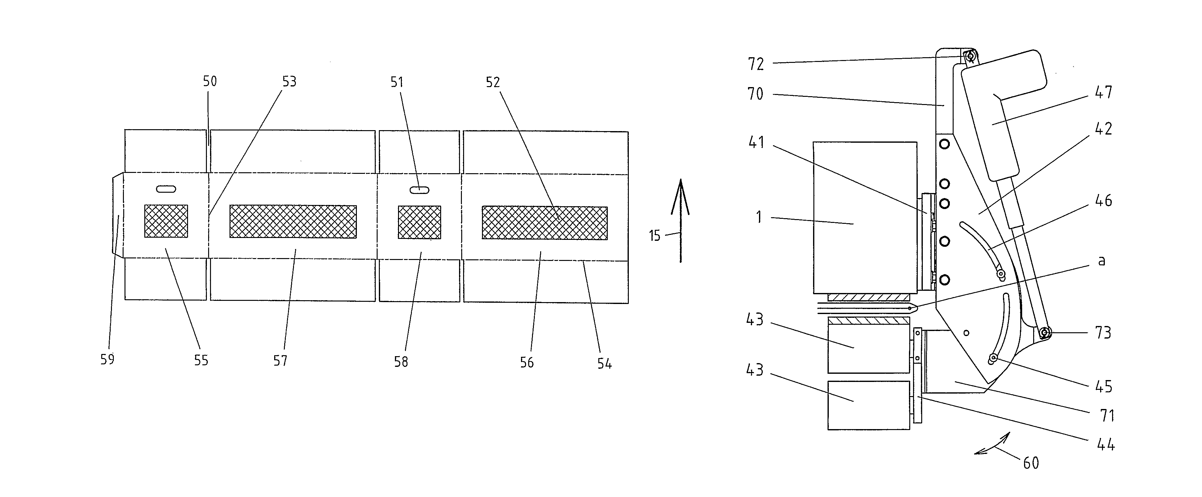
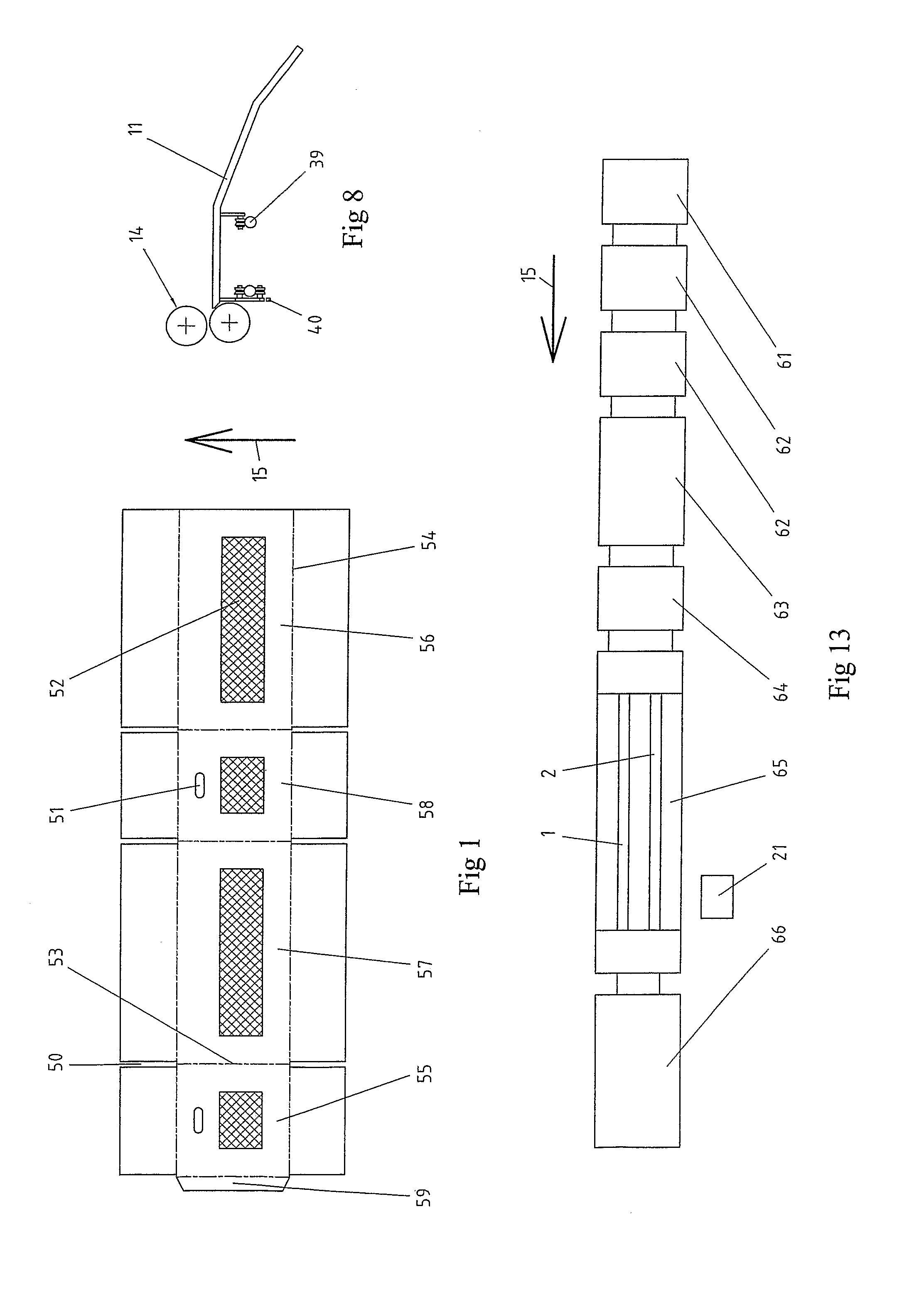
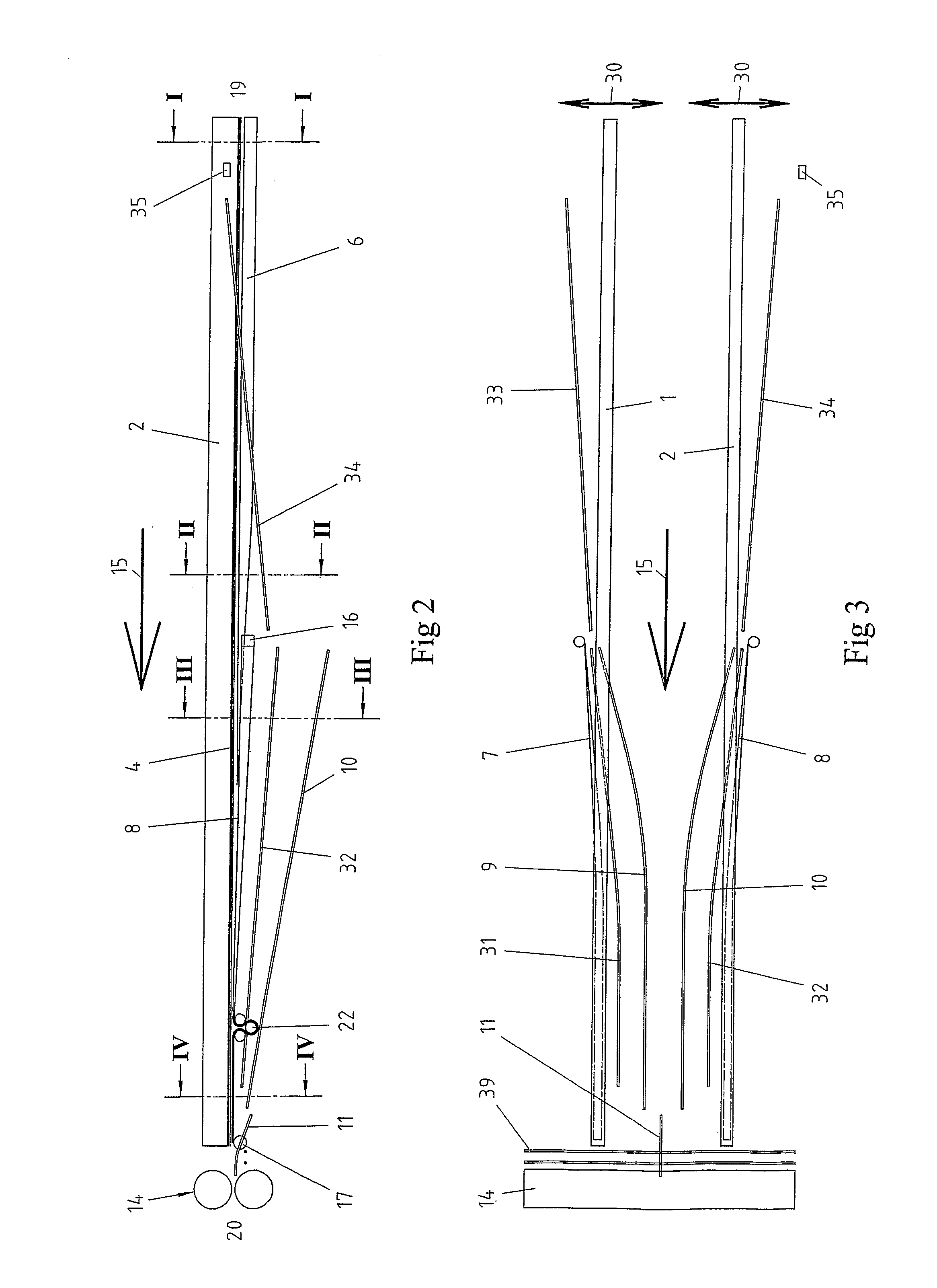
[0034]With reference first to FIGS. 2 and 3, which schematically illustrate the construction of the folding unit, the folding unit comprises a pair of parallel, right-hand and left-hand folding beams 1,2, which extend continuously from the inlet 19 of the folding unit, that is where the corrugated cardboard sheets 18 are supplied to the folding unit, to the outlet 20 of the folding unit, where the corrugated cardboard sheets 18 are supplied to a pair of rolls 14 or some other device connecting the outer panels 55, 56 of the corrugated cardboard sheet or box blank to each other, as will be discussed in more detail below. The folding beams 1, 2 are movably supported on frames (not shown) of the base plate and can be moved sideways, that is transversely to the conveying direction 15 of the corrugated cardboard sheets 18, by means of associated actuators (not shown), as schematically illustrated in FIG. 3 and indicated by arrows 30 in this figure. The actuators are, for example, a pair ...


PUM


Abstract

A folding unit for corrugated cardboard sheets, the folding unit comprising an inlet and an outlet, a pair of parallel and laterally dispiaceable folding beams, a pair of folding rules arranged under respective folding beams, a par of folding rods fixedly positioned outside respective folding rules and at angle to the respective folding rules, a pair of folding belts arranged under and cooperating with a respective pair of folding rules, a means for supplying and folding two outermost panels of the corrugated cardboard sheet from 0°-90° at the inlet of the folding unit and 90°-180° at the outlet of the folding unit, a pair of wheel stands engaged with respective folding belts, a means for adjusting an angle of said wheel stands to ihe associated conveying belt, and a means for fine adjustment of the angular settings of the wheel stands.

Description

[0001]This application is a 371 of PCT / SE2006 / 001009 filed on Sep. 1, 2006.BACKGROUND[0002]1. Field[0003]The present invention relates to a folding unit for corrugated cardboard sheets in inline production of corrugated cardboard boxes, comprising a pair of parallel and laterally displaceable folding beams each with an endless conveying belt, which folding beams extend from the inlet of the folding unit to the outlet of the folding unit, a pair of folding rules which are arranged under the respective folding beams and which extend from the inlet of the folding unit and towards, but not all the way to, the outlet of the folding unit, a pair of folding rods fixedly positioned outside the respective folding rules and at angle to the respective folding rules, said folding rods being arranged in the folding unit front portion, seen in the conveying direction of the corrugated cardboard sheets, a pair of folding belts which are arranged under and cooperate with a respective folding rule a...

Claims


Application Information

Patent Timeline
IPC IPC(8): B31B5/36B31B1/58B31B50/58
CPCB31B1/36B31B1/58B31B1/62B31B3/00B31B2203/082B31B2201/2683B31B2201/6017B31B2203/003B31B2201/2637B31B50/00B31B50/36B31B50/58B31B50/624B31B2100/00B31B2100/0022B31B2120/30B65B59/02B65B59/001
Inventor WIKLUND, LENNART
Owner EMBA HLDG AB
Learn More