
Forging method and forging apparatus

a forging method and forging technology, applied in metal-working apparatus, manufacturing tools, forging/hammering/pressing machines, etc., can solve the problems of increasing the number of production processes, uneven thickness, and difficulty in obtaining the desired so as to improve the dimensional precision of forged articles.

Inactive Publication Date: 2011-10-18
DENSO CORP
View PDF9 Cites 0 Cited by
  • Summary
  • Abstract
  • Description
  • Claims
  • Application Information

AI Technical Summary

Benefits of technology

The present invention provides a forging method and apparatus that can improve the dimensional precision of forged articles and reduce machining processes and costs. The method involves applying a first external force to the end face of the workpiece in the axial direction and a second external force to hold the workpiece end face in a recessed / projecting shape. This second external force helps to equalize internal stress at the workpiece end face and allows for uniform plastic flow, reducing underfill and other defects and improving the dimensional precision of the forged article. The forging apparatus includes independent pressing and holding means that can generate the second external force independently. The use of multiple independent pressing and holding means can further improve the dimensional precision of the forged article.

Problems solved by technology

Further, in the general forging method, obtaining a forged article of the desired dimensional precision is difficult, so the forged shaped article is finished by machining it in a separate process to give it a desired dimensional precision.
When performing this additional machining to secure the desired dimensional precision, there is the problem of that the machining increases the number of production processes.
However, when making the material of the end face of the workpiece flow to forge it into recessed / projecting shapes, in particular when forming a groove shape not point symmetric with the end face of the workpiece (hereinafter referred to as a “non-point symmetric shape”) (see FIG. 3), the thickness becomes uneven, so it becomes hard to make the internal stress at the different positions inside the material of the workpiece uniform.
In this case, underfill and other defects occur.
Further, the walls of the groove are not formed vertical, but end up being formed at a slant, so there were also the problems that the desired precision could not be secured and the required performance could not be satisfied without machining.

Method used


Image

  • Forging method and forging apparatus
  • Forging method and forging apparatus
  • Forging method and forging apparatus

Examples


Embodiment Construction

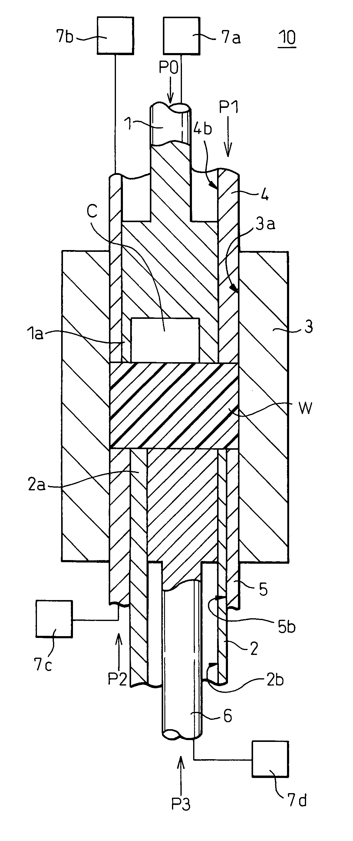
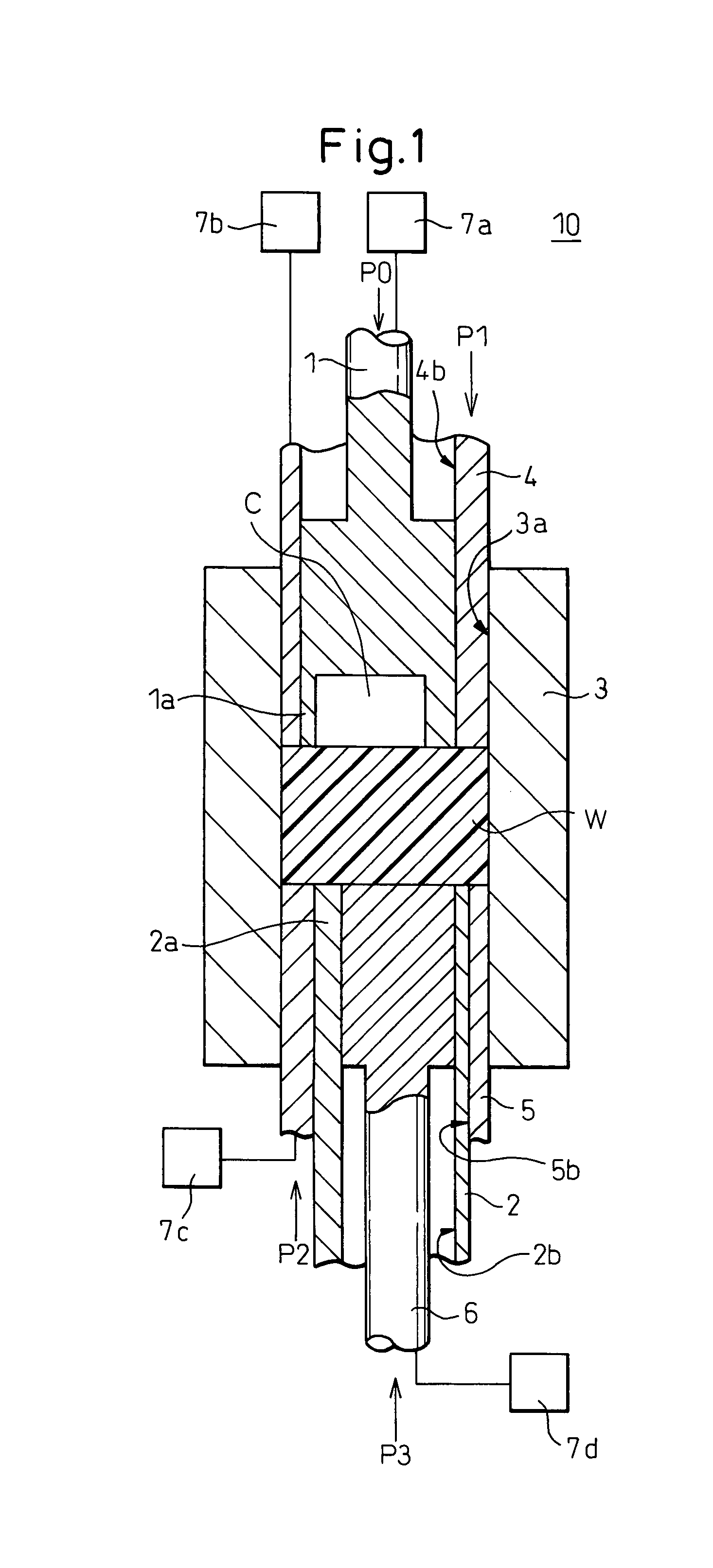
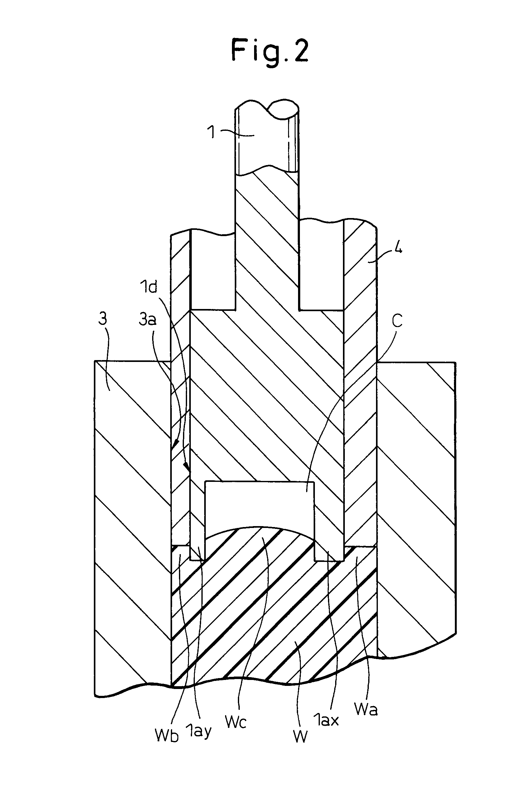
[0031]Below, embodiments of the present invention will be explained based on the drawings. FIG. 1 is a view for explaining the forging method and forging apparatus according to the present invention. FIG. 2 is an enlarged cross-sectional view of a top punch of FIG. 1. FIG. 5 is a view showing the precision of a groove of a shaped article forged by a forging method and forging apparatus according to the present invention using actual measurement values. FIG. 7 is a view of the appearance of a workpiece worked by the forging method and forging apparatus according to the present invention.

[0032]First, the forging apparatus according to the present invention will be explained. In FIG. 1, 10 shows the forging apparatus according to the present invention. 1 shows a top punch forming a die top part, 2 shows a bottom punch forming a die bottom part, 3 shows a die, W shows a columnar workpiece, and C shows a die cavity. Reference numeral 4 is a first pressing and holding means independent fr...


PUM

PropertyMeasurementUnit
heightaaaaaaaaaa
heightaaaaaaaaaa
heightaaaaaaaaaa

Abstract

A forging method and forging apparatus able to improve a dimensional precision of a forged article and able to reduce the machining processes to a minimum and thereby reduce costs are provided. That is, a forging method placing a workpiece inside of a die, pressing the workpiece by a top part of the die in the axial direction toward the bottom part side of the die, and making the material of the end face of the workpiece flow to form the end face of the workpiece into a recessed / projecting shape, which forging method characterized by using independent pressing and holding means for pressing and holding the workpiece in the axial direction independent for the top part and the bottom part at the time of the press forming.

Description

BACKGROUND OF THE INVENTION[0001]1. Field of the Invention[0002]The present invention relates to a forging method and forging apparatus enabling improvement of the precision of a forged article and reduction of the cost of production.[0003]2. Description of the Related Art[0004]In the past, the method of shaping a forging use material which imparts pressing force to a material made of a metal so as forge the material into a predetermined shape has been known.[0005]Further, in the general forging method, obtaining a forged article of the desired dimensional precision is difficult, so the forged shaped article is finished by machining it in a separate process to give it a desired dimensional precision. When performing this additional machining to secure the desired dimensional precision, there is the problem of that the machining increases the number of production processes.[0006]To solve this problem, there is the technique of ironing the outer circumferential portions of a workpiece...

Claims


Application Information

Patent Timeline
Patent Type & Authority Patents(United States)
IPC IPC(8): B21D22/00B21J13/00
CPCB21J5/02B21J5/06
Inventor YABUKI, TETSUROUSATO, HIDEYUKIFUJII, HIROYUKI
Owner DENSO CORP
Learn More