
Operating lever of vehicular seat

a technology of operating lever and vehicle seat, which is applied in the direction of movable seats, furniture parts, and dismountable/non-movable seats, etc., can solve the problems of pulling the hand of a user grabbing the operating lever, and achieves the effect of seat back, space saving, and high operability

Inactive Publication Date: 2011-10-18
TOYOTA BOSHOKU KK +1
View PDF17 Cites 18 Cited by
  • Summary
  • Abstract
  • Description
  • Claims
  • Application Information

AI Technical Summary

Benefits of technology

The invention is a vehicular seat with an operating lever that can be used to change the position of the seat. The lever is located on the front, back, or sides of the seat and includes two levers that pivot on each other. The lever can be operated to change the seat's position by bending the first lever in two stages around its axial shaft. The lever is designed to fold up when not in use and can be stored in a recess on the seat when not needed. The lever is also designed to have a different pivoting limit angle for the second lever and can be expanded and contracted in length. The seat can be stored in a recess on the rear side of the vehicle floor when not in use. The technical effects of this invention include improved seat positioning and a more convenient and easy-to-use lever design.

Problems solved by technology

Also the operating lever is moved to the front side in accordance therewith, and therefore, there poses a problem that the hand of a user grabbing the operating lever is pulled.

Method used


Image

  • Operating lever of vehicular seat
  • Operating lever of vehicular seat
  • Operating lever of vehicular seat

Examples


embodiment 1

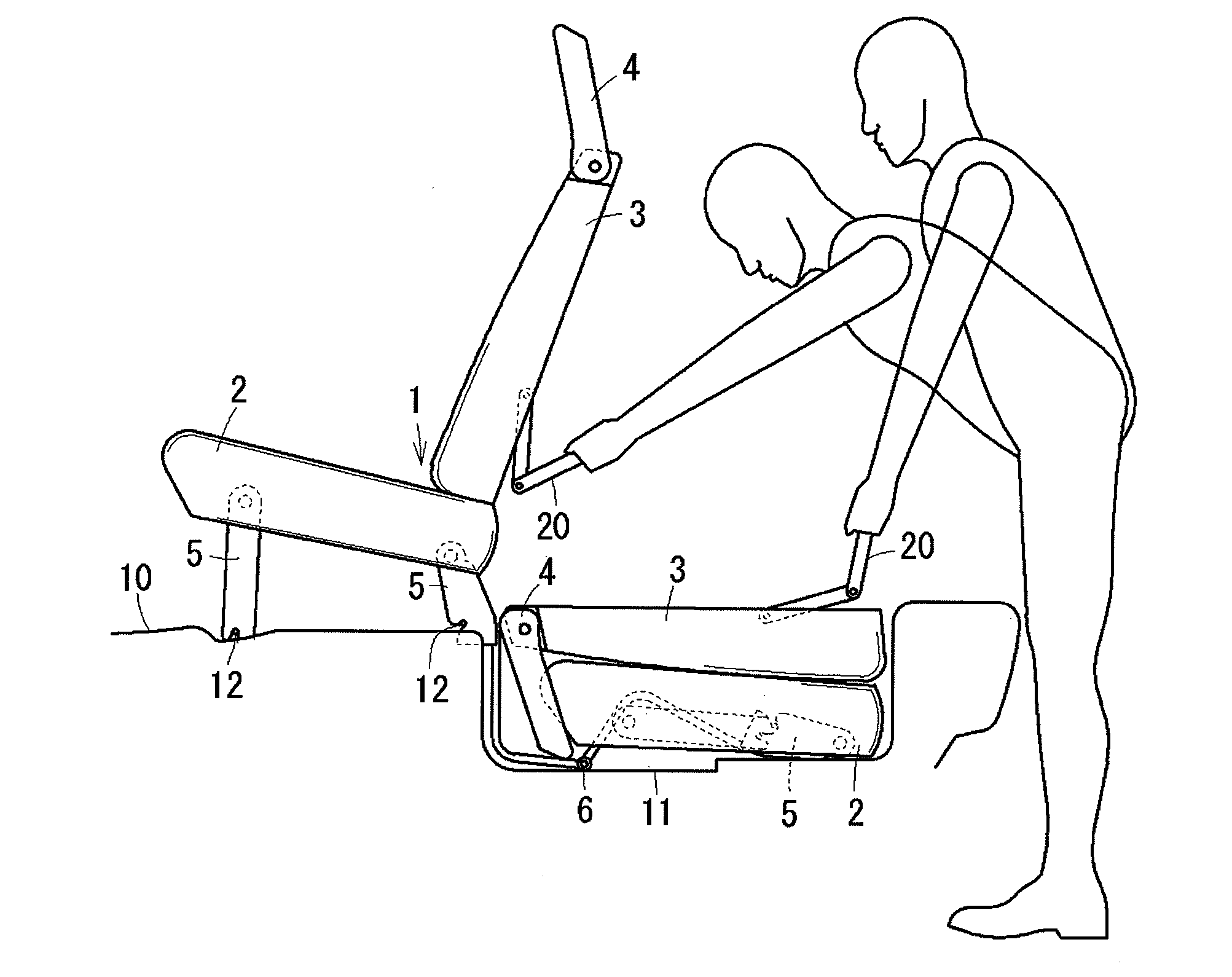
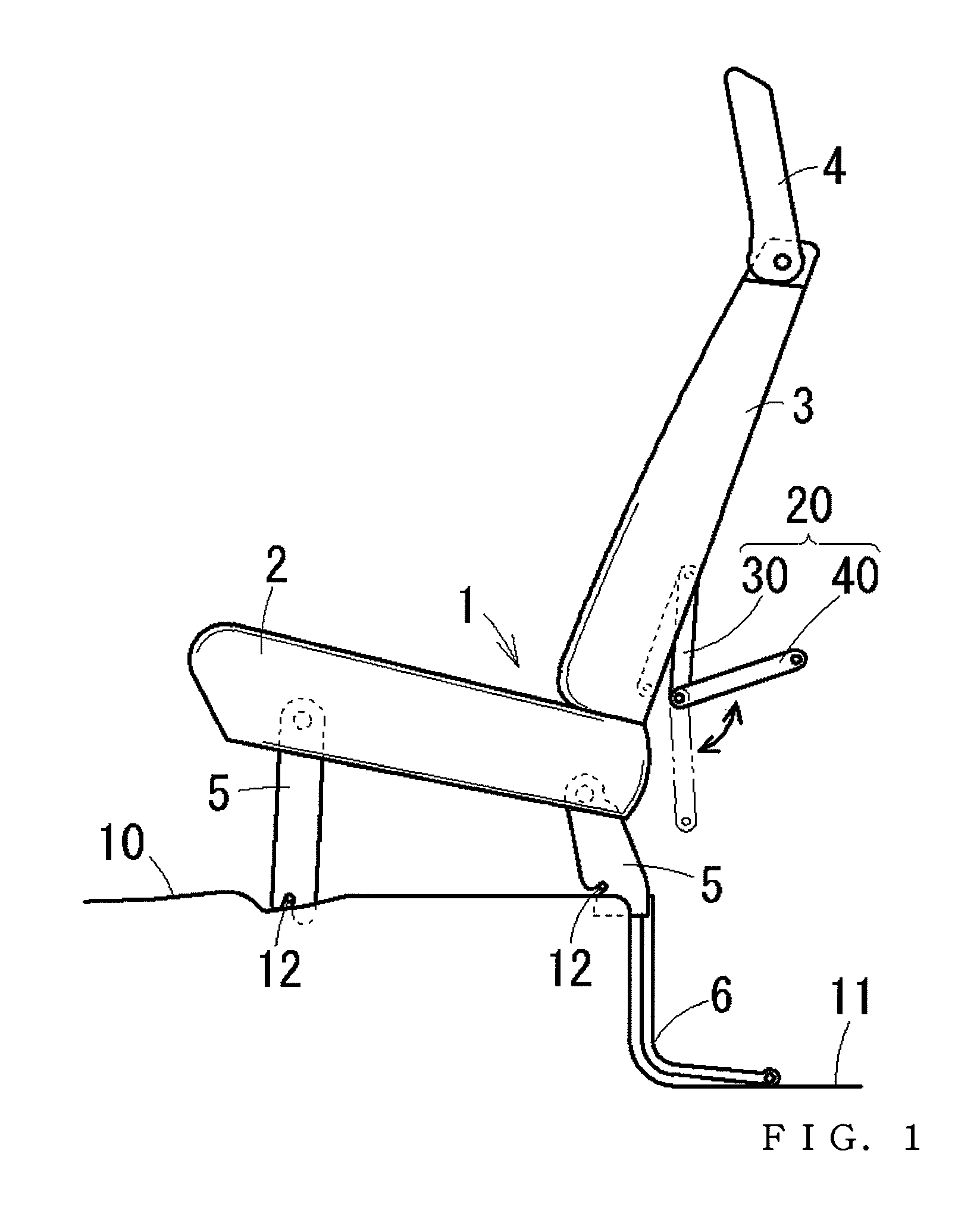
[0031]As shown by FIG. 7, a vehicular seat 1 in Embodiment 1 constitutes a storing seat displaceable between a using position disposed above a vehicular floor 10 and a nonusing position of being stored inside of a storing recess portion 11 recessed on a rear side of the vehicular floor 10 for storing the seat. As shown by FIG. 1, the storing seat 1 includes a seat cushion 2 constituting a seating portion, a seat back 3 constituting a back rest, a head rest 4 for supporting the head portion, and pairs of left and right legs 5, 5 for supporting the storing seat 1 from a lower face thereof on front and rear sides thereof. The two legs 5 on the rear side of the vehicle are connected with link members 6 displaceably supporting the storing seat 1 between a using position and the storing position respectively pivotably between the two legs 5 and a bottom face of the storing recess portion 11. By the two left and right link members 6, the storing seat 1 is made to be displaceable stably bet...

embodiment 2

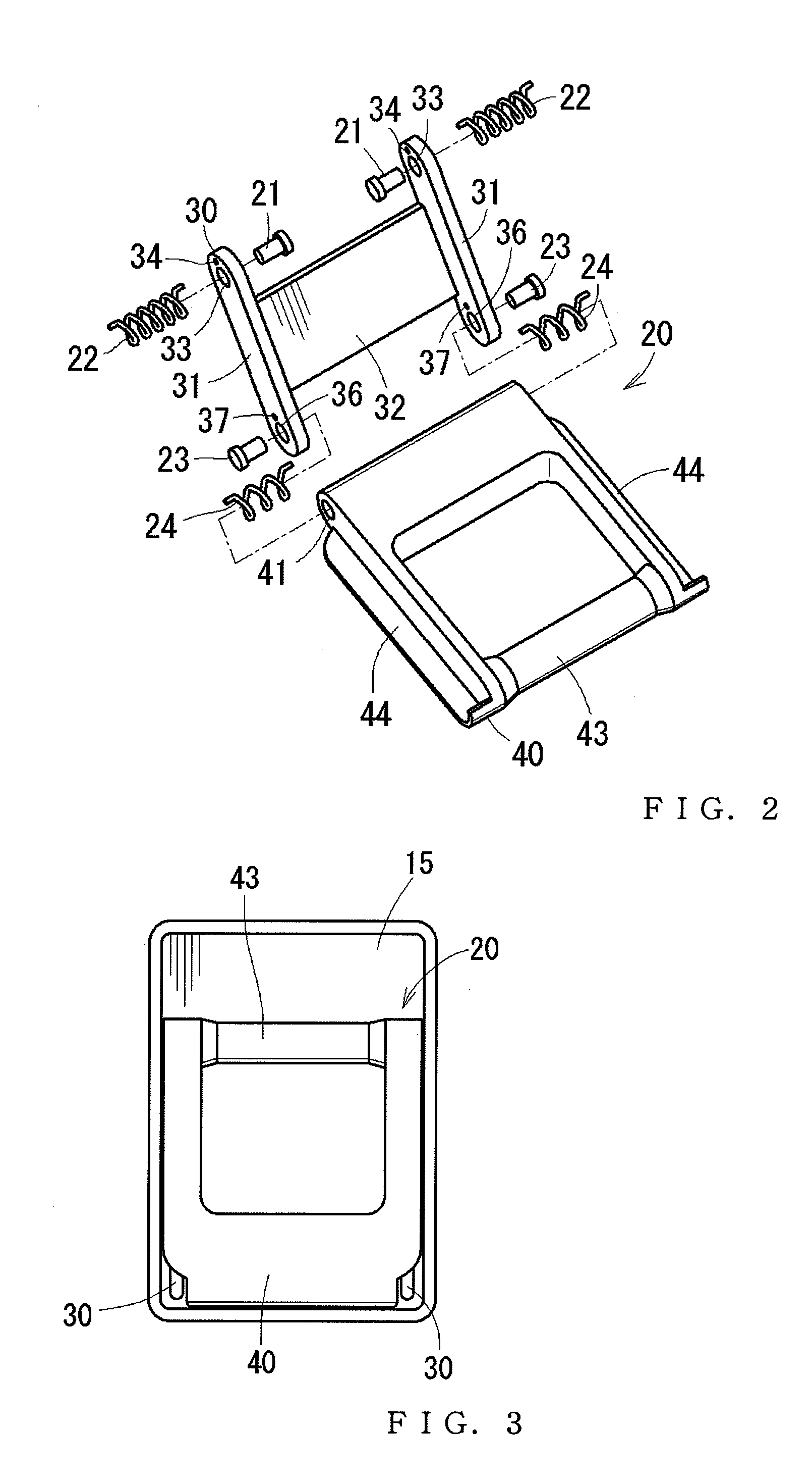
[0041]FIG. 8 is a side view showing Embodiment 2 of an operating lever of a vehicular seat of the invention. The embodiment is characterized in that the angle adjusting lever 40 is constituted to be expandable and contractable in a length direction thereof and a lever length of a position of the grip 43 is able to be changed. Specifically, the angle adjusting lever 40 is constituted by two members of the grip portion 43 and a lever base portion 45. An expanding and contracting mechanism thereof is not particularly limited but a well-known expanding and contracting mechanism can be applied thereto. For example, a mechanism or the like of forming left and right sides of the lever base portion 45 in a shape of a hollow cylinder can be used, inserting guide rods 47 integrally elongated from left and right sides of the grip 43, and is capable of being expanded and contracted in steps by engaging a hook, not illustrated with a plurality of stages of locking portions provided at inside of ...


PUM


Abstract

An operating lever is provided at one of a front face, an upper face, and a back face of a seat including a seat cushion and a seat back. The operating lever may include a first lever having a first end and a second end, and a second lever having a first end and a second end. The second end of the first lever and the first end of the second lever may be pivotably connected to each other, and the first end of the first lever may be pivotably connected to the seat such that the first lever is configured to change an attitude of the seat. In addition, the second end of the second lever may be formed as an operating portion, and when the operating portion is operated in a direction away from the seat, the first lever and the second lever pivot may away from the seat and the attitude of the seat is adjusted.

Description

TECHNICAL FIELD[0001]The present invention relates to an operating lever of a vehicular seat provided at a back face of a seat back of a vehicular seat arranged in a vehicle or the like, connected to a lock mechanism for changing an attitude state of a seat for operating to release lock of the lock mechanism.BACKGROUND ART[0002]As an operating lever of a vehicular seat of this kind, there is, for example, Patent Reference 1. In Patent Reference 1, an operating lever is provided at a storing seat arranged at the rearmost row of a vehicle and capable of being stored to a storing recess portion for storing the seat recessed on a rear side of a vehicular floor when not used. The operating lever is constituted by a member having a section substantially in an L-like shape provided at an upper position of a back face of a seat back, exposed to outside on a side of the back face of the seat back at one end side thereof, and connected with a wire on an inner side of the seat back at other en...

Claims


Application Information

Patent Timeline
Patent Type & Authority Patents(United States)
IPC IPC(8): B60N2/36B60N2/90
CPCB60N2/3011B60N2/442B60N2/3075B60N2/3065B60N2/919B60N2/20B60N2/30B60N2/36
Inventor ITO, MAKOTOOOISHI, YOSHIHIROMURAMATSU, TOMOHIRODAY, ROBERTFUJIMOTO, OSAMU
Owner TOYOTA BOSHOKU KK
Learn More