Syringe having a hinged needle shield

a technology of syringe and shield, which is applied in the direction of intravenous devices, infusion needles, infusion devices, etc., can solve the problems of accidental needle sticks with used needles, unfit needles for further use, and healthcare workers often being unable to use both hands for shielding

Active Publication Date: 2011-10-18
BECTON DICKINSON & CO
View PDF176 Cites 20 Cited by
  • Summary
  • Abstract
  • Description
  • Claims
  • Application Information

AI Technical Summary

Benefits of technology

[0006]A syringe assembly includes a syringe barrel having an elongate body defining a chamber for retaining fluid, an outside surface, and open proximal end and a distal end including a tip having a passageway therethrough in fluid communication with the chamber. Distal end further includes a barrel collar concentrically surrounding the tip. A needle assembly includes a needle cannula having a proximal end, a distal end and a lumen therethrough and a hub having an open proximal end including a cavity therein and a distal end attached to the proximal end of the needle cannula so that lumen of the needle cannula is in fluid communication with the cavity of the hub. The needle assembly is removably attached to the syringe barrel through frictional engagement of the cavity in the hub and the tip on the barrel. A plunger includes an elongate body portion having a proximal portion, a distal portion and a stopper slidably positioned in fluid tight engagement with the inside surface of the barrel for drawing fluid into and driving fluid out of the chamber by movement of the stopper relative to the barrel. The elongate body portion extends outwardly from the open end of the syringe barrel. A collar is rotatably connected to the outside surface of the barrel collar. An elongate needle shield is hingedly connected to the collar. The needle shield includes two side walls defining a longitudinal opening and a back wall between the side walls defining a recess having an interior surface. The needle shield is capable of pivoting from an open position wherein the needle cannula is exposed, to a close needle protecting position wherein the distal end of the needle cannula is within longitudinal opening of the shield. Structure for locking the needle shield in the closed needle protecting position when the needle shield is pivoted into the closed position is provided. The structure includes an arm projecting from the interior surface of the needle shield. The arm has a free end positioned so that when the needle shield is pivoted to the closed position, the needle cannula moves past the free end and is trapped in the needle shield by the arm. Structure for locking further includes a locking projection on the proximal end of the needle shield for lockingly engaging a ledge on the collar when the needle shield is pivoted to the closed position. A protuberance in the recess at the distal end of the needle shield is positioned to contact the hub when the needle shield is pivoted into the closed position to help prevent over-rotation of the needle shield past the needle protecting position. The tab on each of the side walls at the longitudinal opening of the needle shield is provided. The tabs have angled guide surfaces converging toward the longitudinal opening for guiding the needle cannula into the longitudinal opening when the needle shield is being pivoted to the closed position. Spring structure connects the collar and the needle shield for urging the needle shield toward the closed needle protecting position.
[0007]The syringe assembly may further include a rigid elongate needle cover having a distal end and an open proximal end and a side wall therebetween defining the receptacle. The needle covers removably engaged with the hub and contains needle cannula and is intended to protect the needle cannula before the syringe is used for injection and to prevent accidental positioning of the elongate needle shield in the closed position.
[0016]An alternative embodiment of the present invention includes a needle shield assembly for use with a barrel having an elongate body defining a chamber for retaining fluid, an outside surface, an open proximal and a distal end including a tip having a passageway therethrough in fluid communication with the chamber, and a barrel collar concentrically surrounding the barrel tip, a needle cannula having a proximal end, a distal end and a lumen therethrough, and a hub having an open proximal end including a cavity therein and a distal end attached to the proximal end of the cannula so that the lumen is in fluid communication with the cavity. The needle assembly is removable attached to the barrel through frictional engagement of the cavity in the hub and the tip on the barrel. The needle shield assembly comprises a collar rotatably connected to the outside surface of the barrel collar, an elongate needle shield is hingedly connected to the collar, the needle shield includes two side walls defining the longitudinal opening and a back wall between the side walls defining a recess having an interior surface. The needle shield is capable of pivoting from an open position wherein the needle cannula is exposed to the closed needle protecting position wherein the distal end needle cannula is within the longitudinal opening of the needle shield. Structure for locking the needle shield in the closed needle protecting position when the needle shield is pivoted into the closed needle protecting position includes an arm projecting from an interior surface of the needle shield. The arm includes a free end positioned so that when the needle shield is pivoted to the closed position, the needle cannula moves past the free end and is trapped in the needle shield by the arm. Structure for locking further includes a locking projection on the proximal end of the needle shield for locking engaging a ledge on the collar when the needle shield is pivoted to the closed position. A protuberance in the recess at the proximal end of the needle shield is positioned to contact the hub when the needle shield is pivoted in the closed position to help prevent over-rotation of the needle shield past the close needle protecting position. A tab on each of the side walls at the longitudinal opening is provided. Each tab includes an angled guide surface converging toward the longitudinal opening for guiding the needle into the longitudinal opening when the needle shield is being pivoted to the closed position. A spring connected to the collar and the needle shield is provided for urging the needle shield toward the closed needle protecting position.

Problems solved by technology

Accidental needle sticks with new unused needle can cause injury and render the needle unfit for further use.
Accidental needle sticks with a used needle can transmit disease.
Thus, healthcare workers are often unable to use both hands for shielding the needle cannula.
However, until the needle is shielded or properly disposed of, it presents a potential danger to other people.

Method used


Image

  • Syringe having a hinged needle shield
  • Syringe having a hinged needle shield
  • Syringe having a hinged needle shield

Examples


Embodiment Construction

[0034]While this invention is satisfied by embodiments in many different forms, there are shown in the drawings and will herein be described in detail, preferred embodiments of the invention with the understanding that the present disclosure is to be considered exemplary of the principles and are not intended to limit the invention to the embodiments illustrated. The scope of the invention will be measured by the appended claims and their equivalents.

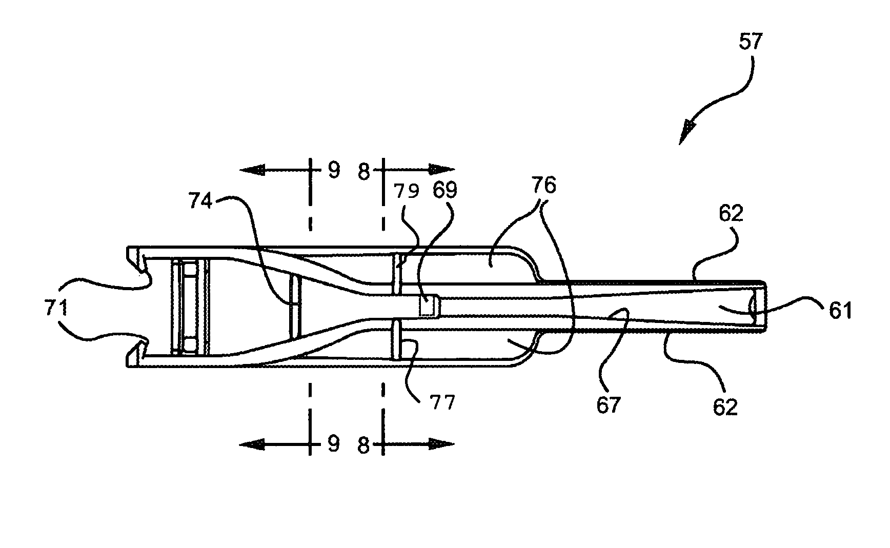
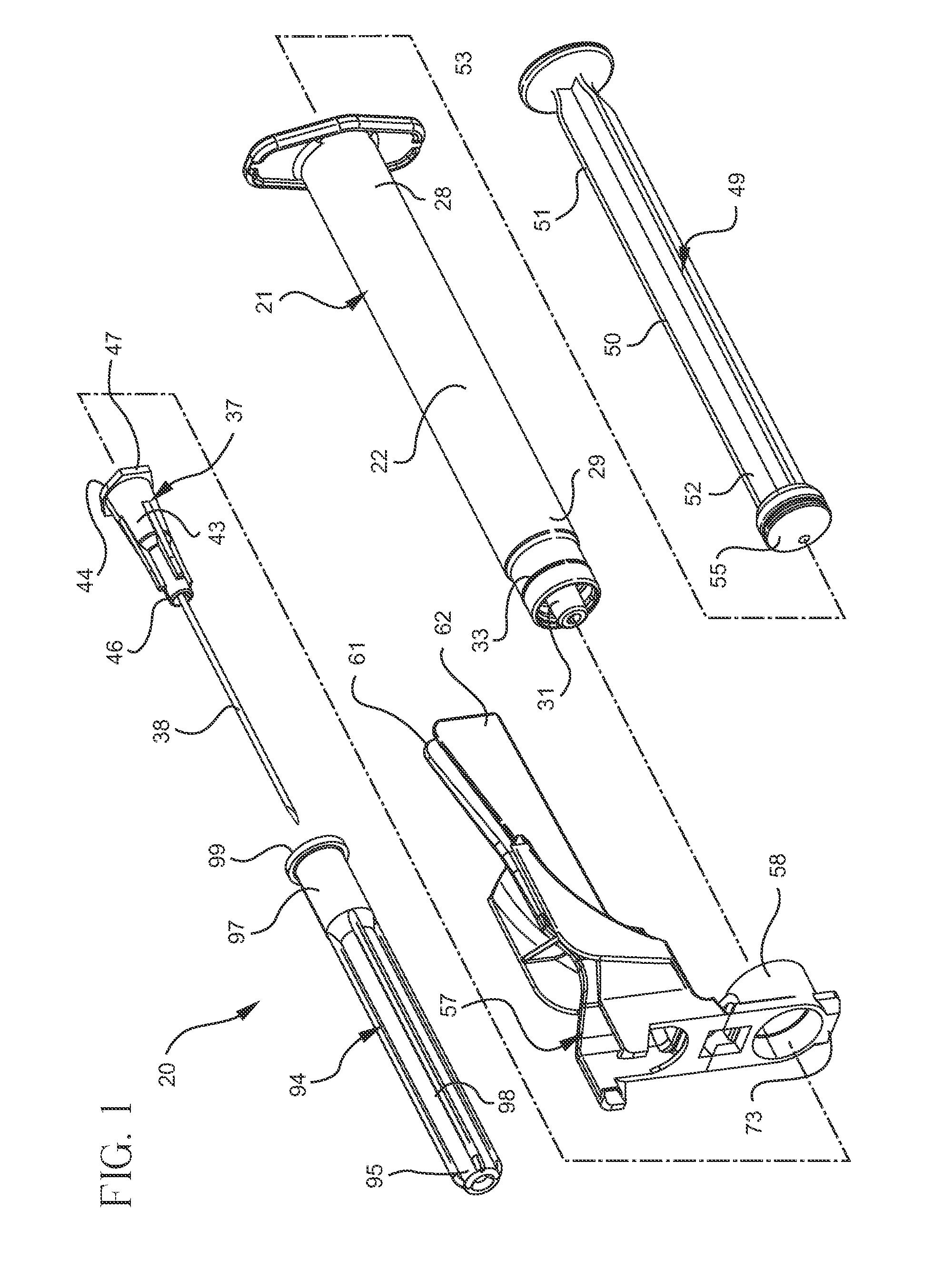
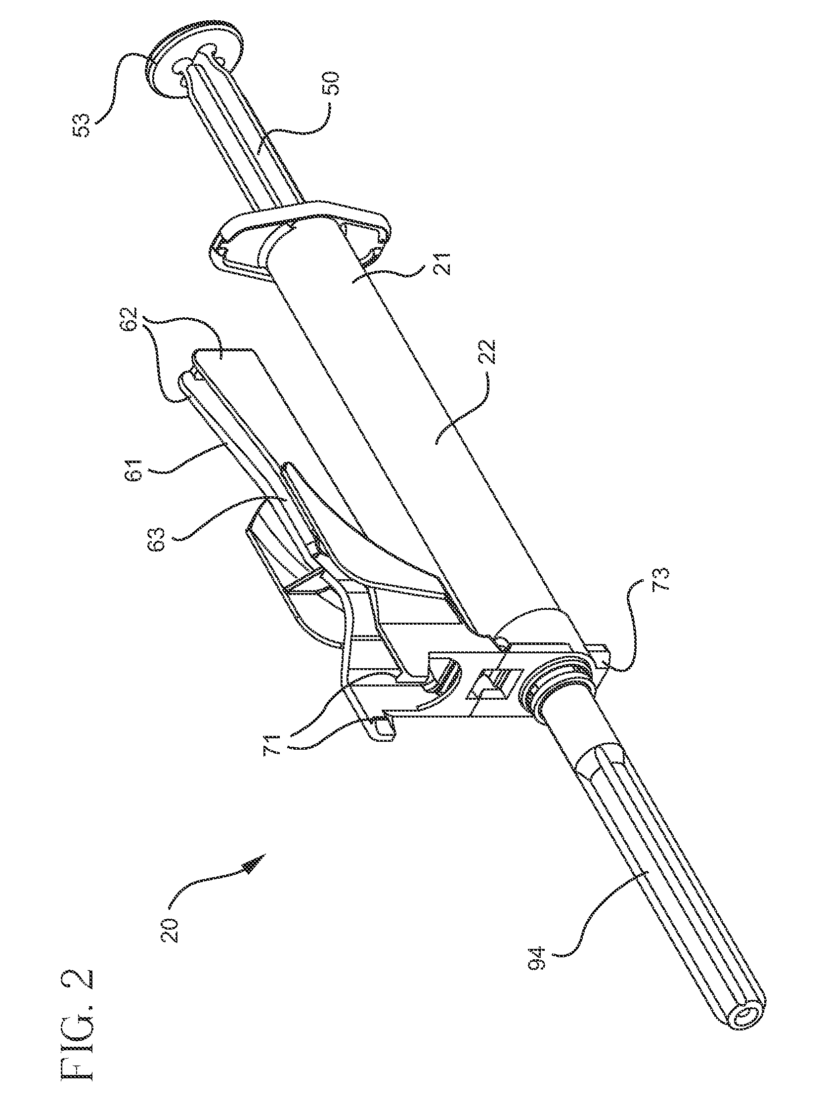
[0035]Referring to FIGS. 1-11, a syringe assembly 20 of the present invention includes a syringe barrel 21 having an elongate body 22 defining a chamber 23 for retaining fluid 25, an outside surface 27 and open proximal end 28 and a distal end 29 including a tip 31 having a passageway therethrough in fluid communication with the chamber. The distal end of the barrel preferably includes a barrel collar 33 concentrically surrounding the tip.

[0036]A needle assembly 37 includes a needle cannula 38 having a proximal end 39 a distal end 40 an...


PUM


Abstract

A syringe assembly includes a syringe barrel having an elongate body, a tip on its distal end surrounded by a barrel collar. A needle assembly includes a needle cannula attached to a hub having a cavity in its open proximal end. The hub is attached to the barrel with the barrel tip in the hub cavity. A plunger having a stopper positioned in fluid tight engagement on the inside of the barrel. A collar is rotatably connected to the outside surface of the barrel collar. An elongate needle shield is hingedly connected to the collar. The needle shield includes two side walls defining a longitudinal opening and a recess. A needle shield is capable of pivoting about the collar from an open position to a closed position wherein the distal end of the needle cannula is in the recess of the needle shield. Structure is provided to lock the needle shield to the collar and to trap the needle cannula in the needle shield when the needle shield is in the closed position. Structure is provided to prevent over-rotation of the needle shield past the needle protecting position and to guide a needle cannula into the recess of the needle shield. An over-center hinge facilitates moving the needle shield to the closed position.

Description

FIELD OF THE INVENTION[0001]The present invention relates generally to single use syringes having safety features and more specifically to a syringe having a hinged needle assembly and a hinged needle shield assembly for use with a syringe.BACKGROUND OF THE INVENTION[0002]Accidental needle sticks with new unused needle can cause injury and render the needle unfit for further use. Accidental needle sticks with a used needle can transmit disease. As a result, most prior art needle assemblies have a needle shield. Some prior art needle shields define a rigid sleeve that can be manually telescoped over a needle cannula. This procedure requires a healthcare worker to hold the syringe barrel in one hand and the shield in the other. Some medical procedures require the application of pressure to the penetration site after the needle has been removed. Thus, healthcare workers are often unable to use both hands for shielding the needle cannula. In these situations, workers merely deposit the ...

Claims


Application Information

Patent Timeline
Patent Type & Authority Patents(United States)
IPC IPC(8): A61M5/32
CPCA61M5/3216A61M5/3202A61M2005/3217
Inventor LIM, KIANG HENGGARDNER, CHRISTOPHER E.
Owner BECTON DICKINSON & CO
Why Eureka
Try Eureka