

Garment bag
- Summary
- Abstract
- Description
- Claims
- Application Information
AI Technical Summary
Benefits of technology
Problems solved by technology
Method used
Image

Examples
first embodiment
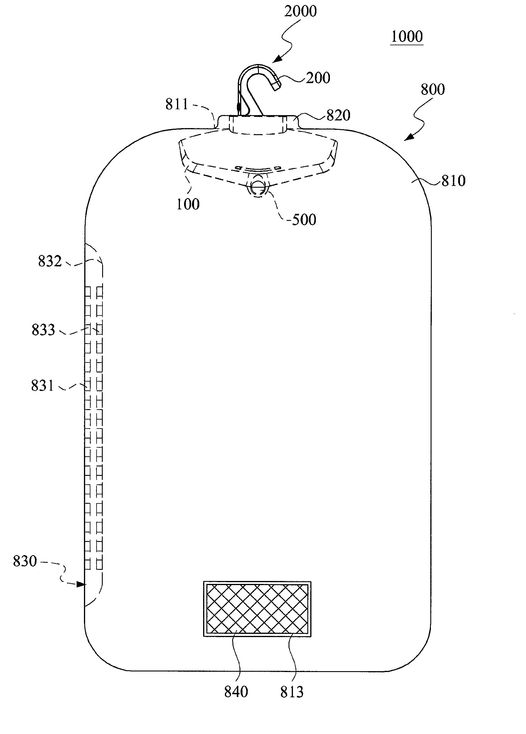
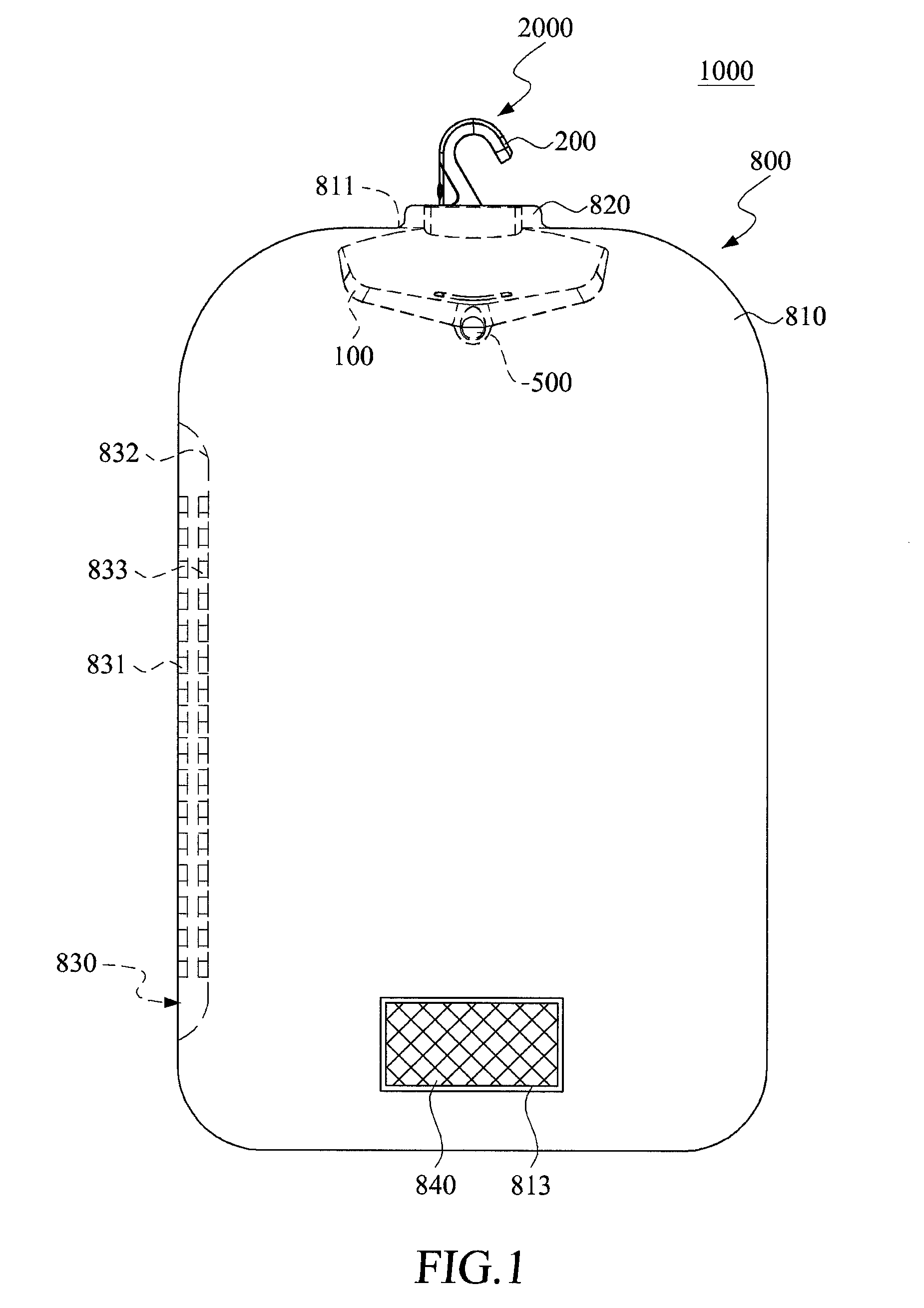
[0019]FIG. 1 is a schematic view of an ozone device of the present invention. As illustrated, the ozone device 1000 accordingly includes an ozone generator 2000 and a garment bag 800. The ozone generator 2000 is capable of generating ozone while the garment bag 800 is connected to the ozone generator 2000 to define a chamber so that dresses can be kept therein.
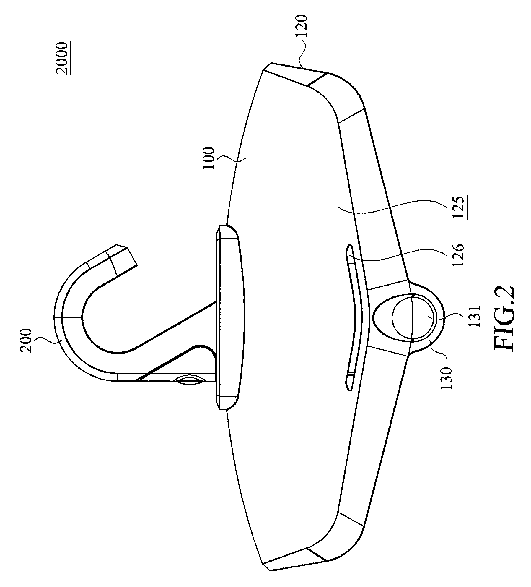
[0020]The garment bag 800 further includes a zipper structure 830 for fastening an opening for access into the chamber. The ozone generator 2000 includes a casing 100 for disposing within the garment bag 800, a hanging unit 200 and a suspending rod unit 500. The zipper structure 830 is pulled downward to uncover the opening via which the ozone generator 2000 can be inserted into the garment bag 800 such that the hanging unit 200 projecting outward from a top portion of the garment bag 800 and is adapted to be hung onto a suspension member (as shown in FIG. 7). Under this condition, the garment bag 800 and the casing 100 do not...
second embodiment
[0034]In second embodiment, please refer to FIG. 6, which the ozone generator 2000a is not disposed within the bag body 810. The ozone generator 2000a includes a communication tube 150. One end of the communication tube 150 is connected to the casing 100a of the ozone generator 2000a, and the other end is sleeved over to the seal unit 820a. Therefore, the ozone generated by the ozone generator 2000a is transmitted to the inner side of the bag body 810 of the garment bag 800 via the communication tube 150. The bag body 810 has a hanging element 860 projecting outward from a top portion thereof. The hanging element 860 can be hung on a suspension member, such as the rail 4100 shown in FIG. 7.
[0035]Please refer to FIGS. 1 and 5, the zipper structure 830 is disposed on the side of the bag body 810 to prevent the ozone leaking out from the zipper structure 830. The dresses 6000 (shown on FIG. 7) can be hung on the ozone generator 2000 in the bag body 81 via the zipper structure 830.
[0036...
third embodiment
[0045]In the third embodiment shown in FIG. 8, upon activation of the circulating fan 400, the ozone from the casing 100 is outputted into the garment bag 800 via the first and third ventilation vents 111, 126 when the ozone flows along the circulation path P without passing through the second ventilation vents 121. Later, the ozone flows back into the casing 100 via the second end 3120 of the fluid tube 850 and the first end 3110 connected fluidly to the respective second ventilation vent 121 on the wall 120. Since the ozone generated by the ozone generator 2000 circulates within the chamber defined cooperatively by the garment bag 800 and the casing 100 repeatedly, most of the ozone circulates within the garment bag 800 for a relatively long time. In the present invention, the ozone generator 2000 can be controlled to operate for short period of time, but the circulating fan 400 for a longer period of time to circulate the ozone for a relatively long time to deodorize the dress. T...
PUM
 Abstract
Description
Claims
Application Information