Microscope for observing a sample in the bright field illumination by transmitted light or in fluorescence-contrast epi-illumination

a microscope and light transmission technology, applied in the field of microscopes for observing objects, can solve the problems of inability of customers to select different fluorescence wavelengths, add-on systems, and relatively complicated, and achieve the effect of improving the ergonomics of the process, increasing the throughput of objects per observer and microscope, and improving the throughput of objects

Active Publication Date: 2011-10-18
CARL ZEISS MICROSCOPY GMBH
View PDF21 Cites 4 Cited by
  • Summary
  • Abstract
  • Description
  • Claims
  • Application Information

AI Technical Summary

Benefits of technology

[0035]The principal advantage of the invention described above is that the ergonomics of the process are improved in comparison with the state of the art and the throughput of objects per observer and microscope is substantially increased. Potential sources of error in operation are eliminated as nearly as possible.
[0036]The fluorescence unit can be added to light microscopes in a simple manner because of its modular design.
[0037]The scope of the invention includes a microscope of the type specified initially, in which
[0038]a fluorescence excitation light source, an illumination optical system, a filter set comprising at least one excitation filter and at least one emission filter, and a beamsplitter are combined into a fluorescence unit, and
[0039]of the fluorescence unit, the beamsplitter and the emission filter are mounted so they are movable, so that
[0040]in a first end position of movement the beamsplitter and the emission filter are out of the imaging beam path of the microscope and in a second end position of movement they are in the imaging beam path between the microscope objective and the microscope tube.

Problems solved by technology

This add-on system has the disadvantage that it is relatively complicated.
There is a further disadvantage that because of a mechanical separation of a solidly built-in filter set and a solidly built-in light source it is impossible for the customer to select different fluorescence wavelengths.

Method used


Image

  • Microscope for observing a sample in the bright field illumination by transmitted light or in fluorescence-contrast epi-illumination
  • Microscope for observing a sample in the bright field illumination by transmitted light or in fluorescence-contrast epi-illumination
  • Microscope for observing a sample in the bright field illumination by transmitted light or in fluorescence-contrast epi-illumination

Examples


Embodiment Construction

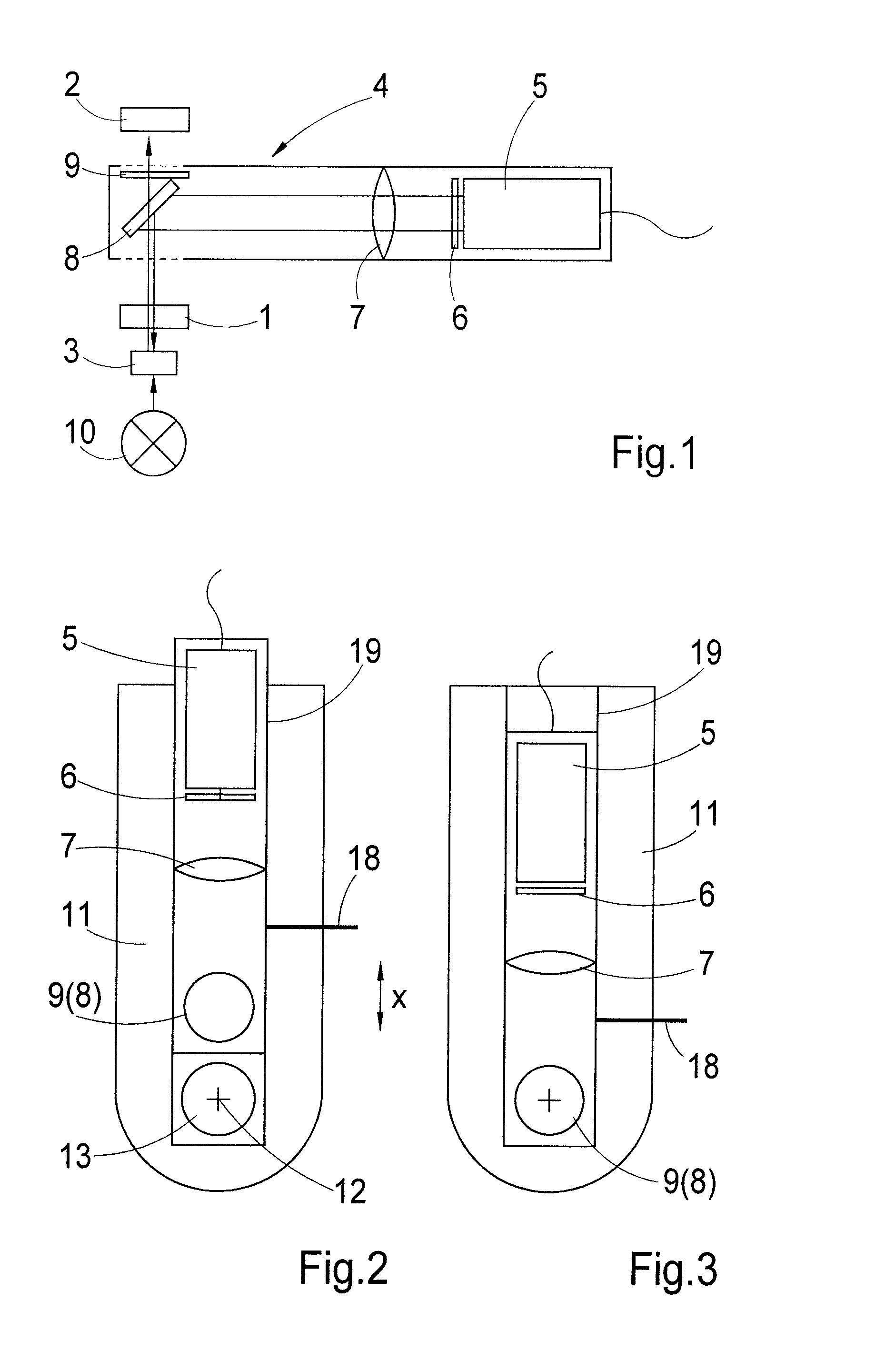
[0053]FIG. 1 shows, symbolically, the major components of the microscope beam path in connection with the description of the invention. These are the microscope objective 1 and the microscope tube 2. Likewise an object 3 being observed.

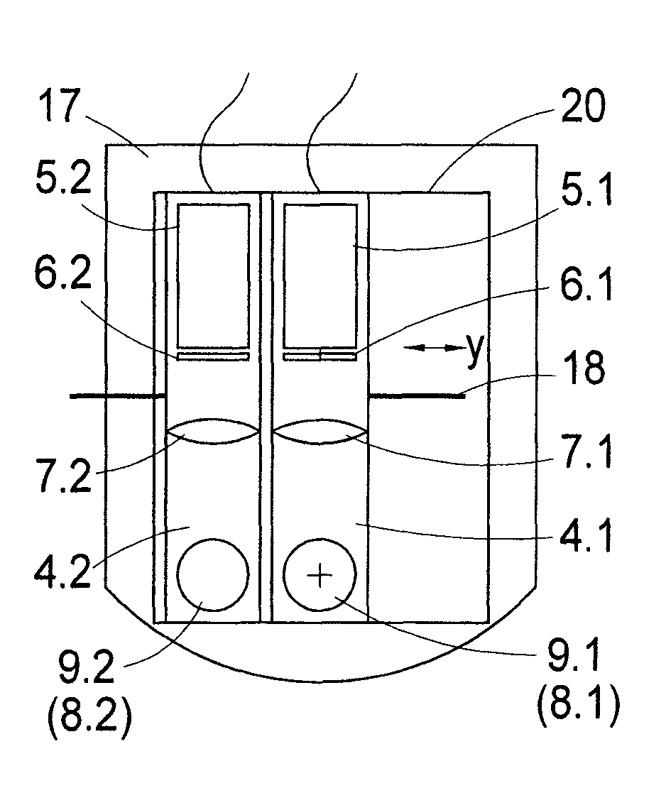
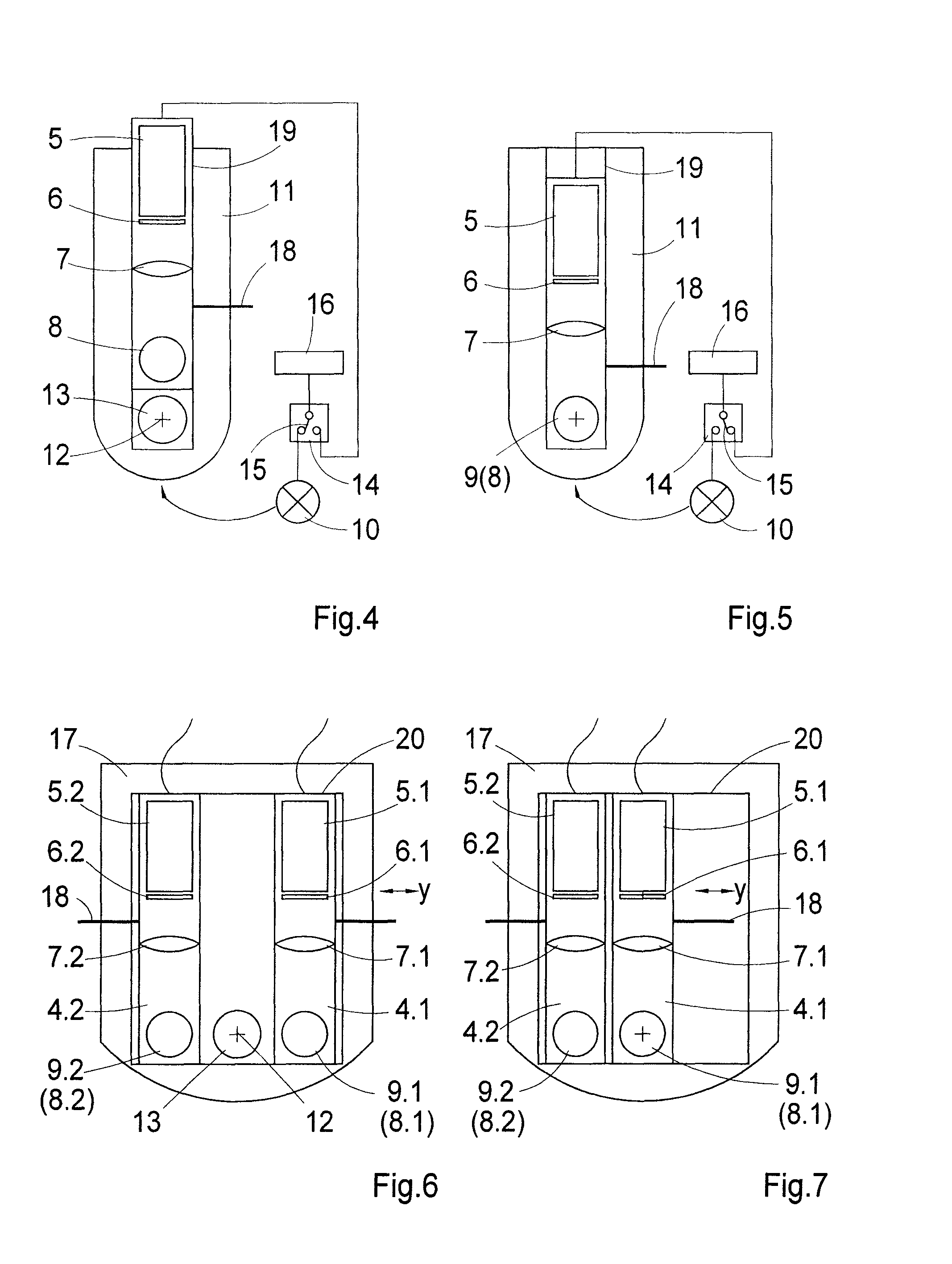
[0054]It is possible to observe the object 3 in incident-light fluorescence contrast by means of the fluorescence unit 4 according to the invention, shown in a side view in FIG. 1. For that purpose the fluorescence unit 4 has:[0055]an LED 5, which, for example, emits light of a wavelength about 470 nm,[0056]an excitation filter 6, which in this case is transparent only to light of wavelengths from 450 nm to 490 nm,[0057]an illumination optical system 7, which provides for illuminating the object 3 with light coming from the LED 5,[0058]a beamsplitter 8, in which the dividing layer reflects excitation radiation with wavelength 500 nm, and[0059]an emission filter 9, which transmits only the emission radiation >510 nm.

[0060]The wavelengths stated refer s...


PUM


Abstract

A microscope for observing an object selectably using the bright-field transmitted light contrast procedure or the incident-light fluorescence contrast procedure. During the bright-field transmitted light contrast procedure, an illumination beam path is directed from a bright-field light source to the object and an imaging beam path is directed from the object through the microscope objective into the microscope tube, which includes a fluorescence unit that includes a fluorescence excitation light source, an illumination optical system, a filter set having at least one excitation filter and at least one emission filter, as well as a beamsplitter. The fluorescence unit is mounted movably, so that in a first end position of movement the beamsplitter and the emission filter are out of the imaging beam path of the microscope and in a second end position of movement they are in the imaging beam path between the microscope objective and the microscope tube.

Description

RELATED APPLICATION[0001]The current application claims the benefit of priority to German Patent Application No. 10 2007 027 084.6 filed on Jun. 12, 2007. Said application is incorporated by reference herein.FIELD OF THE INVENTION[0002]The invention concerns a microscope for observing an object selectably using the bright-field transmitted light contrast procedure or the incident-light fluorescence contrast procedure.BACKGROUND[0003]In microscopes, particularly in light microscopes for observing objects with the bright-field transmitted light contrast procedure, a microscope beam path is directed from a bright-field light source through the object and through the microscope objective into the microscope tube.[0004]Microscopes that are further developed for observing the object in the incident-light fluorescence contrast procedure also have a fluorescence system comprising essentially the following components:[0005]a multispectrally emitting light source, such as an HBO arc lamp with...

Claims


Application Information

Patent Timeline
Patent Type & Authority Patents(United States)
IPC IPC(8): G02B21/06
CPCG02B21/088G02B21/12G02B21/14G02B21/16
Inventor NOLTE, ANDREASBOCHER, THOMASFAHLBUSCH, INGO
Owner CARL ZEISS MICROSCOPY GMBH
Why Eureka
Try Eureka